Split type core locking device

A split-type, oil cylinder technology, applied in metal processing equipment, metal rolling, manufacturing tools, etc., can solve problems such as billet pushing into the rolling mill, capillary in and out of the running route conflicts, etc., to achieve hot rolling process improvement, process layout reasonable effect

Active Publication Date: 2010-06-30
TAIYUAN HEAVY IND
View PDF0 Cites 7 Cited by
  • Summary
  • Abstract
  • Description
  • Claims
  • Application Information

AI Technical Summary

Problems solved by technology

[0004] from figure 1 It can be seen that the current core-holding device only has a small opening on the upper right, and the capillary can only be put in through the opening. After the work is completed, the capillary will be taken away from the original path, which makes the entry and exit routes of the capillary conflict. Limit the process layout of the whole hot rolling equipment
[0005] In the production of seamless steel pipes, it is necessary to transport the capillaries horizontally from the top of the core holding device, and then transport the capillaries out from the top horizontally after the work is completed, so as to achieve the best process flow; on the other hand, in the production of seamless steel pipes , sometimes it is necessary to use the tube pushing trolley to push the billet into the rolling mill, but the current core holding device can no longer be used to push the billet into the rolling mill, because the current core holding device is a closed the structure of

Method used


Image

  • Split type core locking device
  • Split type core locking device
  • Split type core locking device

Examples


Embodiment Construction

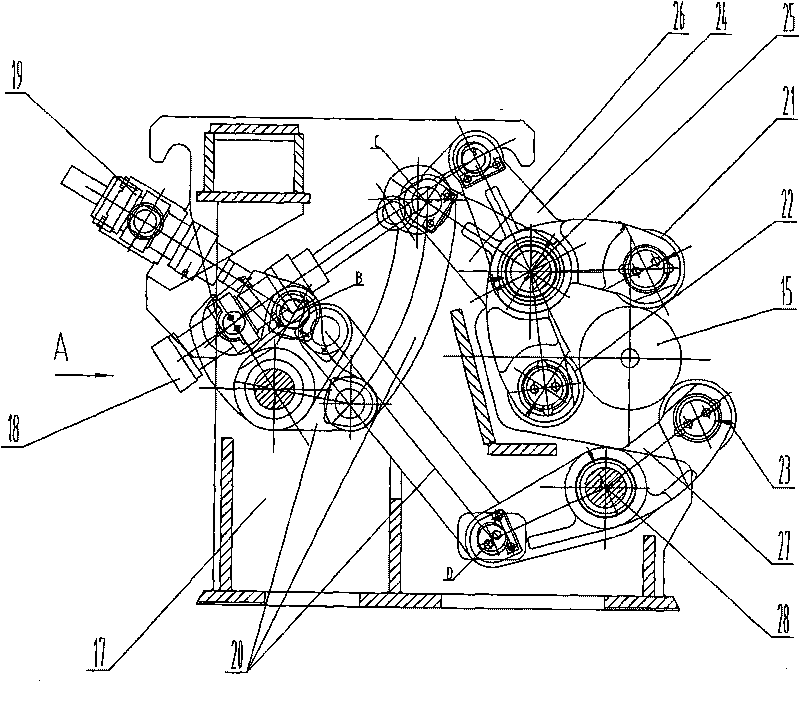
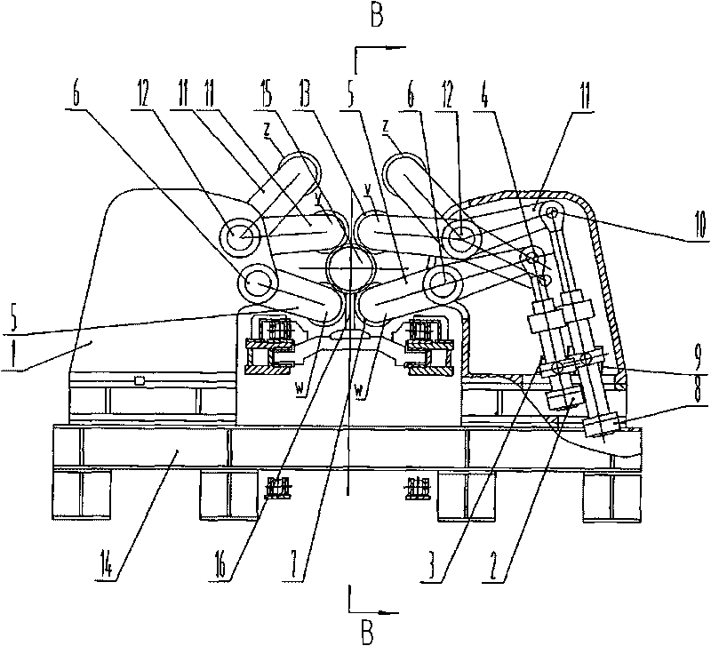
[0018] like image 3 , 4 As shown, a split-type core-holding device includes: a base, an oil cylinder connected to the base, and a holding roller connected to the oil cylinder through a swing arm; the base 1 is two, symmetrically arranged on a large base 14; the There are four oil cylinders, four holding rollers, two lower swing oil cylinders 2 and two upper swing oil cylinders 8 are symmetrically installed on the two bases 1 respectively, and the two lower swing oil cylinders 2 pass through the two lower swing arms respectively. 5 are respectively connected with two lower holding rollers 7, and two upper swing oil cylinders 8 are respectively connected with two upper holding rollers 13 through two upper swing arms 11.

[0019] The trunnion of the hem oil cylinder 2 is hinged on the hem bearing seat 3, and the hem bearing seat 3 is fixed on the base 1, and the piston rod earring of the hem oil cylinder 2 is hinged on the hem arm 5 through the hem pin shaft 4 At one end, the ...


PUM


Abstract

The invention provides a split type core locking device, which relates to a lock core device for a perforator and a pipe rolling machine. The invention solves the problems of the existing core locking device that the capillary can not get in and out transversally; the technological layout of the hot rolling equipment is unreasonable. The split type core locking device comprises bases, oil cylinders and snubber rolls, wherein the oil cylinders are connected with the bases; the snubber rolls are connected with the oil cylinders through swinging arms. The split type lock core device is characterized in that the number of the bases is two, and the bases are symmetrically arranged on the large base; the number of the oil cylinders is four, two lower swinging oil cylinders and two upper swinging oil cylinders are respectively symmetrically arranged on the two bases, the two lower swinging oil cylinders are respectively connected with two lower snubber rolls through two lower swinging arms, and the two upper swinging oil cylinders are respectively connected with two upper lock cores through two upper swinging arms. As the four snubber rolls are symmetrically arranged on the large base, the opened split type lock core device is formed, the capillary can get in and out from the upper part, and a pipe pushing trolley can push the capillary into the pipe rolling machine from the middle part, therefore the technological layout of the hot rolling equipment is reasonable.

Description

technical field [0001] The invention belongs to steel rolling machinery, in particular to a core holding device used in piercing machines and pipe rolling machines in the production of seamless steel pipes. Background technique [0002] In the current production of seamless steel pipes, a special mechanical device that holds the ejector rod and capillary on the exit side of the piercing machine to stabilize the piercing process, or holds the mandrel and capillary on the entrance side of the rolling mill to stabilize the rolling process is called core holding. device. [0003] The current core holding device, such as figure 1 , 2 As shown: it is composed of a base 17, two oil cylinders 18, 19, a connecting rod mechanism 20 and three holding rollers 21, 22, 23. The middle trunnion of the oil cylinder 18 is installed on the base 17, and the piston rod of the oil cylinder 18 The earring is hinged on one end of the upper swing arm 24, the other end of the upper swing arm 24 is...

Claims


Application Information

Patent Timeline
Patent Type & Authority Applications(China)
IPC IPC(8): B21B25/02
Inventor 张良夫
Owner TAIYUAN HEAVY IND
Why Eureka
Try Eureka