Cutter

A technology for cutting machines and cutting slots, which is applied in the direction of metal sawing equipment, sawing machine devices, sawing machine attachments, etc. It can solve the problems of complex structure, laborious rotation, and increased cost, and achieve simplified overall structure, easy operation, and reduced production costs. cost effect

Active Publication Date: 2010-06-30
POSITEC POWER TOOLS (SUZHOU) CO LTD
View PDF0 Cites 7 Cited by
  • Summary
  • Abstract
  • Description
  • Claims
  • Application Information

AI Technical Summary

Problems solved by technology

[0003] However, in the actual operation process, it was found that the saw mechanism is pivotally arranged on the workbench through the support arm, which makes the structure more complicated, and the base is provided with a rotating workbench with a rotating structure, so that the whole cutting machine has many parts , the structure i

Method used


Image

  • Cutter
  • Cutter
  • Cutter

Examples


Embodiment Construction

[0048] The present invention will be further described below in conjunction with the accompanying drawings and preferred embodiments.

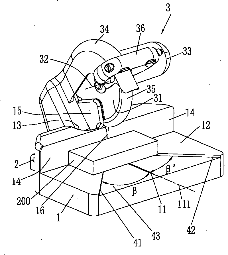
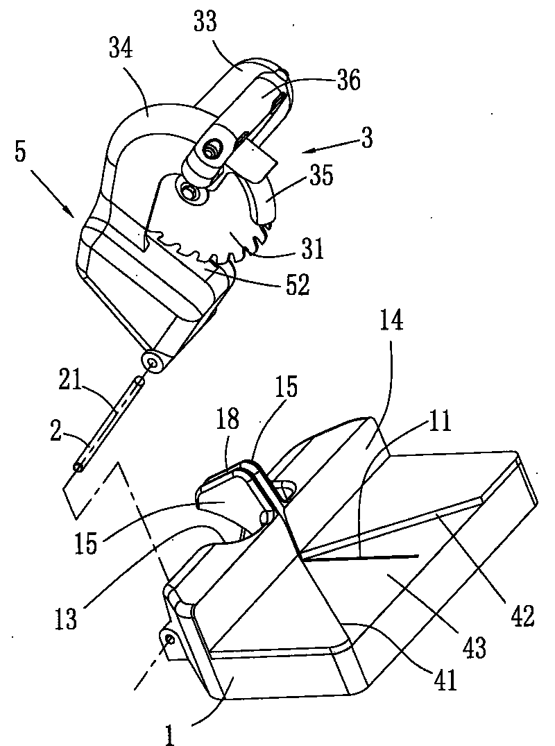
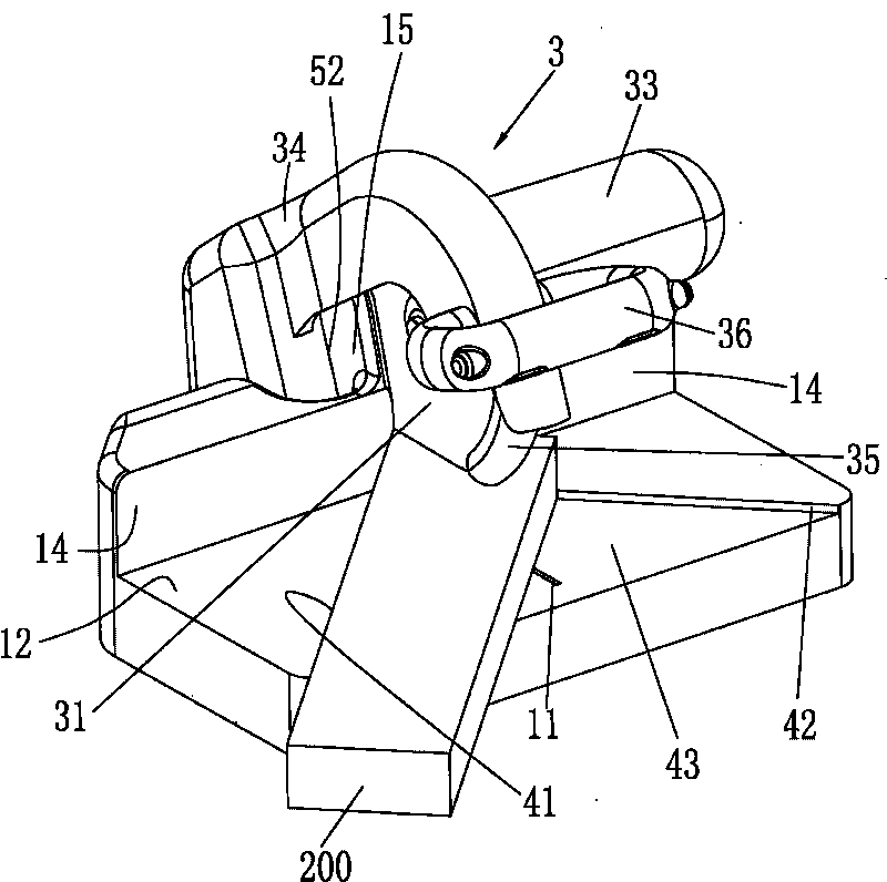
[0049] see Figure 1 to Figure 10 Shown, the first preferred embodiment of the present invention. Such as figure 1 and figure 2 As shown, the cutting machine includes a workbench 1 and a saw mechanism 3 matched with the workbench 1, wherein the saw mechanism 3 is directly rotatably connected to the workbench 1 through a pivot 2, so that the structure of the cutting machine of the present invention is simple, Compact and low cost.

[0050]The saw mechanism 3 includes a saw blade 31, a motor (not shown) that drives the rotation of the saw blade 31, a fixed guard 34, a movable guard 35, and a handle 36, wherein the saw blade 31 is mounted on a saw blade shaft (not shown) The saw blade shaft has a saw blade shaft axis 32; the motor is rotatably arranged in the motor housing 33 for driving the saw blade 31 to rotate around the saw blade shaft ...


PUM


Abstract

The invention discloses a cutter, which comprises a worktable and a sawing mechanism that is pivoted with the worktable, wherein the sawing mechanism comprises a motor, a saw bit and a fixing shield; the motor is positioned above the worktable; the saw bit is driven by the rotation of the motor; the fixing shield is used for at least wrapping part of the saw bit. A first support area or a second support area is matched and connected with the worktable, therefore, 90-degree vertical cutting or left and right chamfering is realized only by placing the work piece in the first support area or the second support area without changing or adjusting any structure. Therefore, the whole structure of the cutter is greatly simplified, the production cost is lowered, and the operation is easy and convenient.

Description

technical field [0001] The invention relates to a cutting machine, in particular to a cutting machine capable of realizing oblique cutting. Background technique [0002] As a cutting tool, the traditional cutting machine has a wide range of applications and can be used to cut many metal or non-metal materials, and the cutting is fast and convenient. The cutting machine generally includes a base, a saw mechanism with a motor and a saw blade located above the base, and a guardrail arranged on the base for positioning the workpiece, wherein a circular rotary with a cutting groove that rotates horizontally is provided approximately in the middle of the base. A table, the saw mechanism is pivotably connected to the rear side of the rotary table by means of a support arm. The guardrail is a positioning plate, and the positioning plate is composed of reference plane parts at both ends and an arc-shaped connecting part whose middle part deviates from the cutting groove. When in us...

Claims


Application Information

Patent Timeline
IPC IPC(8): B23D47/02B23D47/04B23D59/00B23D45/14B23D45/04
CPCB23D45/042B23D47/025B27G5/023
Inventor 沃伦·布朗哈利·索默格雷厄姆·格哈德
Owner POSITEC POWER TOOLS (SUZHOU) CO LTD
Why Eureka
Try Eureka