Manufacturing process for main shaft of large water turbine

A manufacturing process and technology of hydraulic turbines, which are applied in the directions of shafts, mechanical equipment, hydropower generation, etc., can solve the problems of hydraulic turbine manufacturers unable to provide products to users in time, high cost, and long production cycle.

Inactive Publication Date: 2010-06-30
HARBIN ELECTRIC MASCH CO LTD
View PDF0 Cites 10 Cited by
  • Summary
  • Abstract
  • Description
  • Claims
  • Application Information

AI Technical Summary

Problems solved by technology

The disadvantage of this manufacturing method is that the cost is high and the production cycle is long.
Moreover, the production capacity of the manufacturing plant that can provide large forgings is limited. When the delivery date cannot be met, the turbine manufacturing plant will not be able to provide products to the user in time.

Method used


Image

  • Manufacturing process for main shaft of large water turbine
  • Manufacturing process for main shaft of large water turbine
  • Manufacturing process for main shaft of large water turbine

Examples


Embodiment Construction

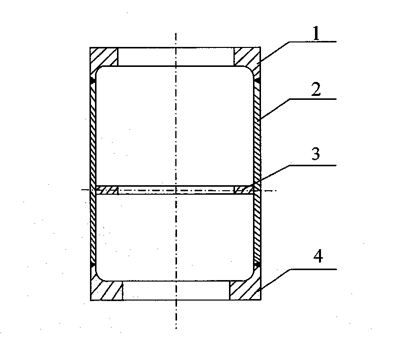
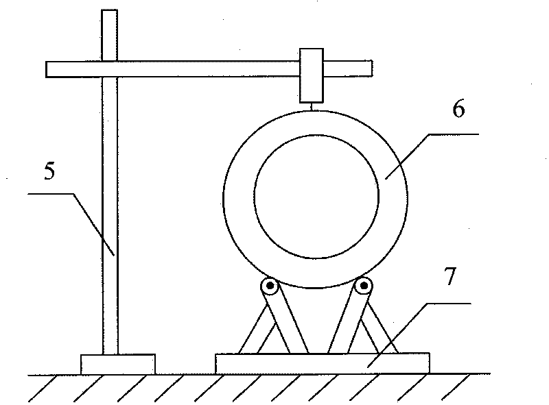
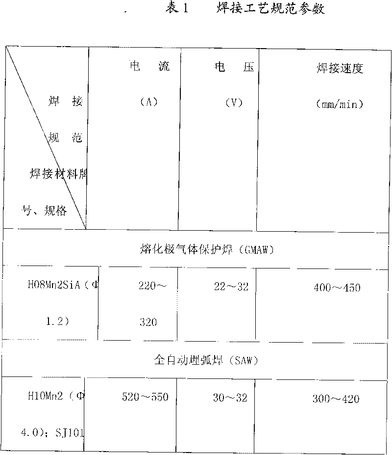
[0007] A manufacturing process for the main shaft of a large hydraulic turbine. The shaft body is divided into two sections in the length direction, and each section is divided into two parts. It is formed by cold pressing with a 3,000-ton hydraulic press. For thick steel plates with a thickness of more than 100mm, the steel plate is stress-relieved once before forming. Heat treatment, the steel plate blank used for the forming of the single-lobe shaft body has enough forming allowance, and the unilateral allowance is 350-400mm; after the single-lobe shaft body is formed, the forming allowance is cut off, and the two-lobed cylinder is welded into one section The shaft body, the longitudinal weld of the shaft body adopts submerged arc welding; after welding, an intermediate stress relief heat treatment is performed on the single-section shaft body. The inner and outer circles are roughly machined; the welding groove between the two shaft bodies is processed, and the two shaft bo...


PUM


Abstract

The invention relates to a manufacturing process for a main shaft of a large water turbine. The main shaft is divided into two sections along the length direction, and each shaft body is divided into two cylindrical bodies subjected to cold-press molding by using a 3000 ton level oil press. The cylindrical bodies are welded to form a shaft body, and submerged-arc welding is adopted for the longitudinal welding of the shaft body. After welding, an intermediate stress relief heat treatment is performed on the single shaft body. The two shaft bodies assembled and welded by using a method of narrow-gap submerged arc welding. After being welded, the inner circle of the shaft body is machined to a size in accordance with the drawing. The welding line between the shaft body and the flange I and between the shaft body and the flange II are welded by using the narrow-gap submerged arc welding. After welding, a final stress relief heat treatment is performed on the main shaft. UT, MT flaw detections are performed on the welding line to realize final machining of the main shaft. The invention has the advantages of reasonable and brief assembling process, high production efficiency, low cost and the like.

Description

technical field [0001] The invention relates to a manufacturing process method for a main shaft of a large water turbine. Background technique [0002] At present, the main shafts of large hydraulic turbines in our country are all main shafts with forged welding structure. That is, the shaft body and the flange are forged separately, and the shaft body part adopts a forged structure. After rough machining, the blank of the hydraulic turbine main shaft is manufactured by welding. Through mechanical processing in the turbine manufacturing plant, the finished turbine main shaft that meets the size and tolerance requirements of the design drawings is achieved. The forged structure of the main shaft body is a conventional manufacturing method adopted by the main shaft forging factory. The disadvantages of this manufacturing method are high cost and long production cycle. Moreover, the production capacity of the manufacturing plant that can provide large forgings is limited. Wh...

Claims


Application Information

Patent Timeline
Patent Type & Authority Applications(China)
IPC IPC(8): F16C3/02F03B11/00
CPCY02E10/226Y02E10/20
Inventor 闫海滨李滨陈明乔宏来田井成
Owner HARBIN ELECTRIC MASCH CO LTD
Why Eureka
Try Eureka