Electric auxiliary heating device of air conditioner

A heating device and electric auxiliary technology, applied in heating methods, lighting and heating equipment, space heating and ventilation, etc., can solve the impact on life and property safety, deformation and falling off of plastic parts of the air outlet frame, and insensitive response of thermal trippers And other issues

Inactive Publication Date: 2010-06-30
GUANGDONG MIDEA ELECTRIC APPLIANCES CO LTD
View PDF0 Cites 11 Cited by
  • Summary
  • Abstract
  • Description
  • Claims
  • Application Information

AI Technical Summary

Problems solved by technology

When the electric control fails, the indoor fan does not turn and the electric auxiliary heating device is turned on, this structure may be insensitive to the response of the thermal release, causing the plastic parts of the air outlet frame to deform and fall off, which may easily cause a fire, which will bring safety belts to the lives and property of the general public. come a big impact

Method used


Image

  • Electric auxiliary heating device of air conditioner
  • Electric auxiliary heating device of air conditioner
  • Electric auxiliary heating device of air conditioner

Examples


Embodiment 1

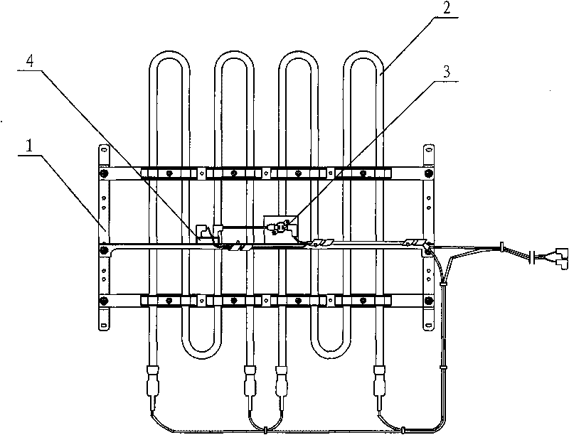
[0016] Embodiment one: see figure 2 , the heating device 2 in the electric auxiliary heating device is installed between the air outlet frame and the evaporator through the bracket 1, the non-self-resetting thermal tripper 4 is located at the upper end of the heating device 2, and the self-resetting thermal tripper 3 is located at the heating device 2 middle. The distance between the non-self-resetting thermal release 4 and the upper end of the heating appliance 2 is generally in the range of 3 to 40mm. When the heating appliance 2 is turned on independently, the non-self-resetting thermal release 4 can most effectively feel the heat of the heating appliance 2, and automatically The reset thermal tripper 3 is located at the side of the heating appliance 2, and the distance from the heating appliance 2 is in the range of 3-40 mm, and feels the heat radiated from the middle of the heating appliance 2. When the non-self-resetting thermal tripper 4 is at the same distance from t...

Embodiment 2

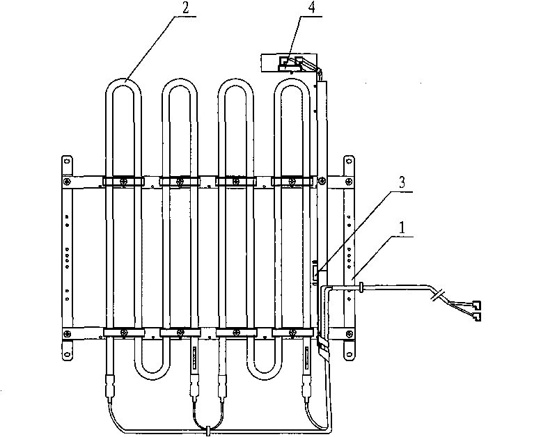
[0017] Embodiment two: if image 3 As shown, both the non-self-resetting thermal tripper 4 and the self-resetting thermal tripper 3 in the electric auxiliary heating device are located on the upper end of the heating device 2, which is also beneficial to protect the self-resetting thermal tripper 3 and improve sensitivity. The heating device 2 is an electric heating tube, and the structural parts not described are the same as those in the first embodiment.

Embodiment 3

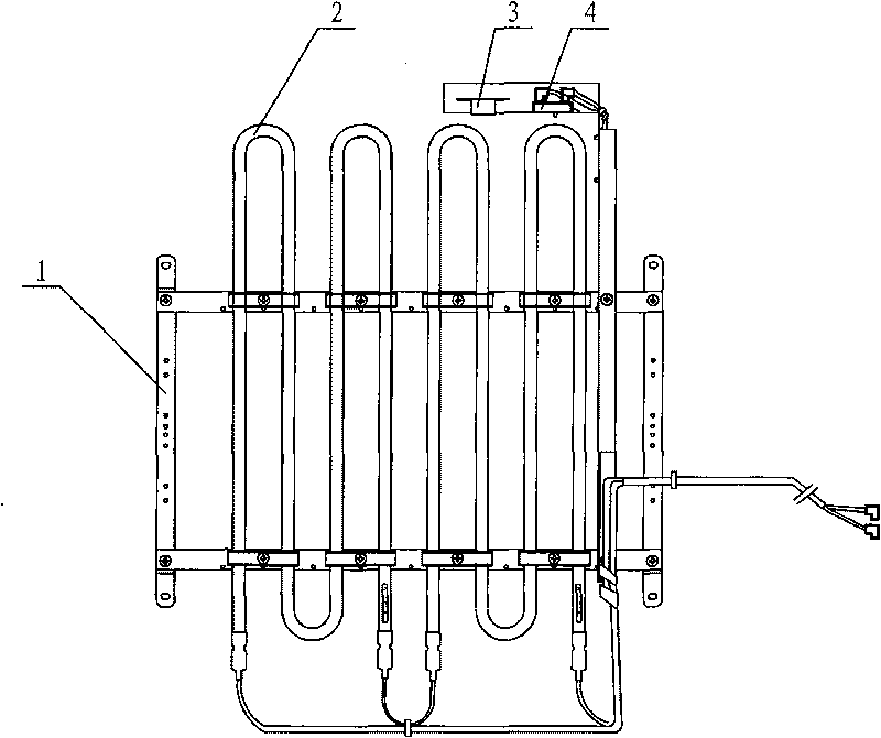
[0018] Embodiment three: as Figure 4 As shown, the non-self-resetting thermal tripper 4 and the self-resetting thermal tripper 3 in the electric auxiliary heating device are both located on the upper end of the heating device 2, and the heating device 2 is a PTC semiconductor, and the structural parts not described are the same as the first embodiment.


PUM


Abstract

The invention discloses an electric auxiliary heating device of an air conditioner, which comprises a heating appliance arranged inside an air-out frame and a self-resetting thermal trip and a non-self-resetting thermal trip, and is characterized in that the non-self-resetting thermal trip is located in the upper end of the heating appliance. The self-resetting thermal trip is located in the upper end, the lateral part or the middle part of the heating appliance. The heating appliance is an electric heating tube or a PTC semiconductor. When in normal use of the air conditioner, the non-self-resetting thermal trip feels the heat radiated by a heat pump and the top of the heating appliance of the electric auxiliary heating device, the temperature is low, the non-self-resetting thermal trip sets a low stated action temperature, thereby the response time of stopping work of the electric auxiliary heating device is shortened, and the deformation of the structure members is reduced. The electric auxiliary heating device of an air conditioner has dedicated design, good performance, security and practicability. The response speed of the non-self-resetting thermal trip is accelerated by changing the position thereof, and the misfire phenomenon caused by the independent starting of the electric auxiliary heating device is fundamentally avoided.

Description

technical field [0001] The invention relates to an electric auxiliary heating device for an air conditioner. The invention belongs to the technical field of manufacturing air conditioners. Background technique [0002] At present, the electric auxiliary heating device used in the field of air conditioning is mainly resistive heating, and its main forms are bare alloy heating wire type and composite tubular heating type, and the other is PTC semiconductor type. At present, the electric auxiliary heating device used in the cabinet is generally installed in front of the evaporator at the air outlet through the bracket 1 to supplement the heating of the heat pump to a certain extent, which can effectively solve the problem of insufficient heating of the heat pump. According to GB 4706.32-2004 "Special Requirements for Safety of Heat Pumps, Air Conditioners and Dehumidifiers for Household and Similar Electrical Appliances", appliances with auxiliary electric heaters for heating ...

Claims


Application Information

Patent Timeline
Patent Type & Authority Applications(China)
IPC IPC(8): F24F11/02
Inventor 向卫华付新
Owner GUANGDONG MIDEA ELECTRIC APPLIANCES CO LTD
Why Eureka
Try Eureka