Air conditioning system and flow control method thereof, and electric flow distributor

A flow distributor and flow distribution technology, applied in flow control of electric devices, refrigeration and liquefaction, refrigerators, etc., can solve the problems of large number of parts, complicated pipeline connections, high manufacturing costs, etc.

Inactive Publication Date: 2013-06-12
三花股份(江西)自控元器件有限公司
View PDF2 Cites 0 Cited by
  • Summary
  • Abstract
  • Description
  • Claims
  • Application Information

AI Technical Summary

Problems solved by technology

[0004] The technical problem to be solved and the technical task proposed by the present invention are to overcome the problems of large number of parts, high manufacturing cost and complicated pipeline connection in the prior art, aiming at using multiple indoor heat exchangers or one indoor heat exchanger The air-conditioning system with multiple heat exchangers provides a flow control method with relatively simple control and low manufacturing cost and the corresponding air-conditioning system, and at the same time provides an electric flow distributor patented for this air-conditioning system

Method used


Image

  • Air conditioning system and flow control method thereof, and electric flow distributor
  • Air conditioning system and flow control method thereof, and electric flow distributor
  • Air conditioning system and flow control method thereof, and electric flow distributor

Examples


Embodiment approach

[0043] Because air-conditioning systems are very common, the same parts as existing air-conditioning technologies, such as fans, solenoid valves, and other conventional components, as well as some conventional control circuits and control methods, will not be introduced here. The difference in technology.

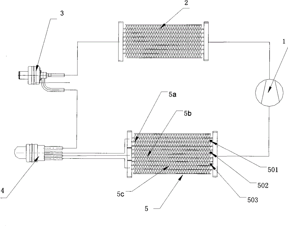
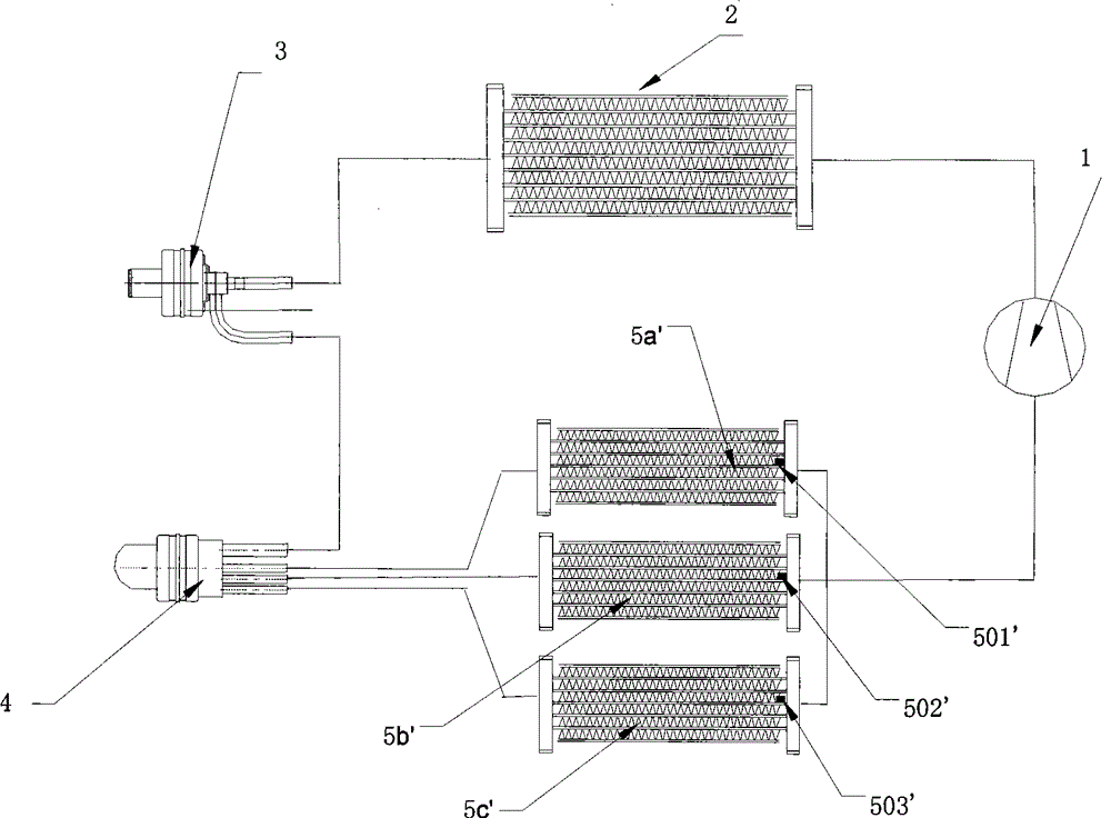
[0044] Such as figure 1 As shown, figure 1 It is a schematic diagram of the first embodiment of the air conditioning system of the present invention. The air conditioning system of the present invention includes a compressor 1, an outdoor heat exchanger 2, an expansion valve 3, an indoor heat exchanger 5, and the indoor heat exchanger 5 consists of three sets of heat exchangers: a first heat exchanger 5a, a second heat exchanger The second heat exchanger 5b and the third heat exchanger 5c are formed in parallel. The advantage of such an indoor heat exchanger is that the heat exchange efficiency of the indoor heat exchanger can be fully utilized and the energy efficiency ratio ...


PUM


Abstract

The invention provides an air conditioning system and a flow control method thereof, and an electric flow distributor for implementing the flow control method. A flow control system of the air conditioning system in the prior art has the defects of high fault rate due to more parts and components and complex pipeline connection, and the like. In the air conditioning system of the invention, a flow distributing system with the electric flow distributor is arranged between an expansion valve and indoor heat exchangers to distribute the flow of a refrigerant to each indoor heat exchanger or eachgroup of heat exchangers of the indoor heat exchanger so as to complete the flow distribution of indoor units of a one-driving-more air conditioning system or the flow distribution of the air conditioning system comprising a plurality of groups of heat exchangers; and the air conditioning system automatically regulates the opening degree of the expansion valve and the flow of the refrigerant, uniformly distributes the flow among all the indoor units or all the groups of heat exchangers, fully develops the heat exchange function of all the indoor units or all the groups of heat exchangers and reduces the waste of heat exchange areas so as to improve the efficiency of the whole air conditioning system.

Description

Technical field [0001] The invention belongs to an air conditioning system, in particular to a flow control method of the air conditioning system, and an electric flow distributor for realizing the flow control method. Background technique [0002] Most of the air-conditioning systems in the prior art include indoor heat exchangers, outdoor heat exchangers, compressors and throttling devices. In some air-conditioning systems with one-to-many systems, in order to improve the heat exchange efficiency of the heat exchanger, the internal refrigerant The distribution of flow rate has always been a technical difficulty; many systems use electronic expansion valves to individually control and distribute the flow rate of each indoor unit, as disclosed in the publication specification of the invention patent application No. 200610145015.2 filed on November 29, 2006 In the solution, each indoor unit is used to intelligently adjust the electronic expansion valve of each indoor unit through ...

Claims


Application Information

Patent Timeline
Patent Type & Authority Patents(China)
IPC IPC(8): F25B1/00F25B49/02F25B41/00F25B41/04G05D7/06
Inventor 胡梅宴
Owner 三花股份(江西)自控元器件有限公司
Why Eureka
Try Eureka