Evaporator and loop type heat pipe applying same

An evaporator and loop technology, applied in the field of loop heat pipes, can solve problems such as reducing the effective pressure difference of loop heat pipes, failure of loop heat pipes, and drying of working fluid, so as to prevent dryness, prolong service life, and ensure permeability Effect

Inactive Publication Date: 2010-06-30
FU ZHUN PRECISION IND SHENZHEN +1
View PDF0 Cites 18 Cited by
  • Summary
  • Abstract
  • Description
  • Claims
  • Application Information

AI Technical Summary

Problems solved by technology

[0003] The capillary structure of the traditional loop heat pipe is attached to the inner tube wall of the loop heat pipe, and the evaporation chamber and the compensation chamber are integrated. When the loop heat pipe is working, the capillary structure located in the evaporation chamber absorbs heat, and the capillary structure of the evaporation chamber absorbs heat. Part of the heat in the evaporation chamber is absorbed by the working fluid in the evaporation chamber, and the rest of the heat is transferred to the capillary structure in the compensation chamber, so that the working fluid in the compensation chamber evaporates, generating a pressure opposite to the predetermined working direction, reducing the heat loss of the loop heat pipe. At the same time, a large number of air bubbles are generated on the surface of the capillary structure of the compensation chamber. These bubbles affect the permeability of the working fluid in the compensation chamber, causing the working fluid in the evaporation chamber to dry out, resulting in a flow interruption phenomenon, so that the loop heat pipe fails.

Method used


Image

  • Evaporator and loop type heat pipe applying same
  • Evaporator and loop type heat pipe applying same
  • Evaporator and loop type heat pipe applying same

Examples


Embodiment Construction

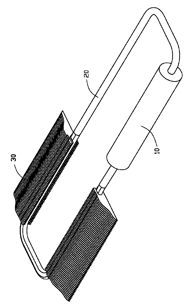
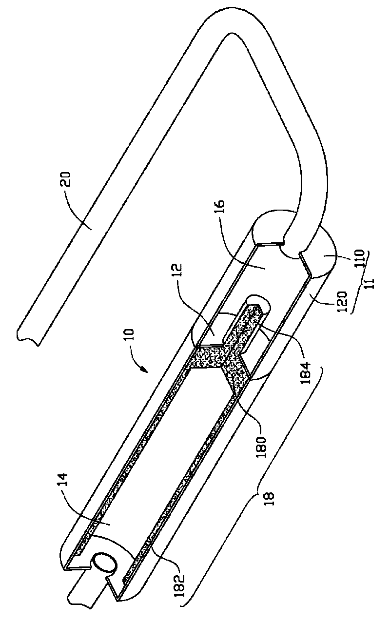
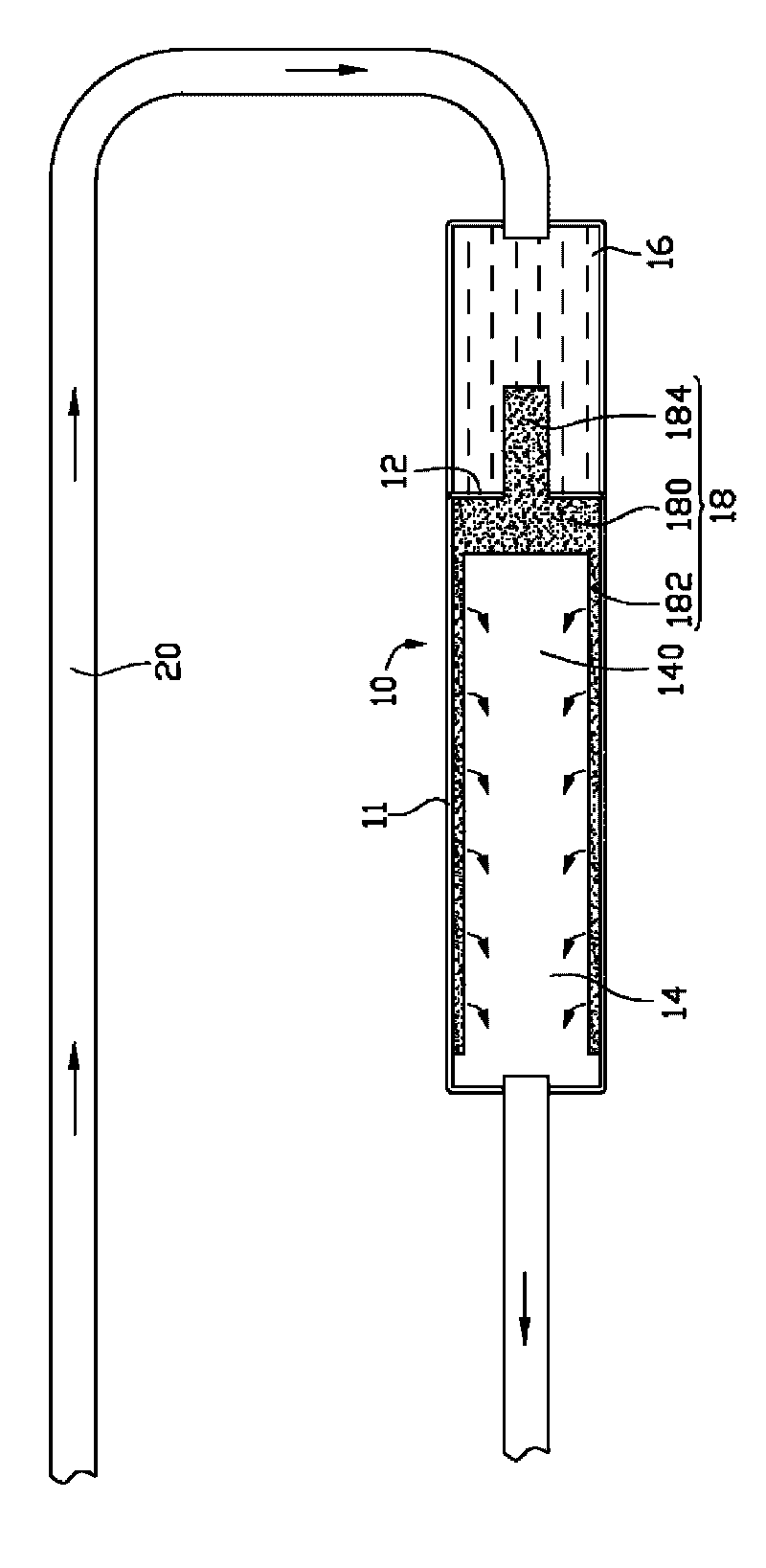
[0012] see figure 1 A loop heat pipe according to a preferred embodiment of the present invention includes an evaporator 10 , pipes 20 connecting opposite ends of the evaporator 10 , and a plurality of cooling fins 30 sleeved on the pipes 20 . The pipeline 20 connects opposite ends of the evaporator 10, so that the evaporator 10 and the pipeline 20 form a sealed circuit. The circuit is filled with working liquid (such as image 3 shown), the working liquid can be water, alcohol, etc. The pipeline 20 can be made of flexible materials compatible with the working fluid, such as copper, aluminum or stainless steel. One end of the evaporator 10 absorbs the heat generated by a heat-generating electronic component such as a CPU, and evaporates the working liquid. The vapor flows out along the pipeline 20 and is cooled by the cooling fins 30 to cool the vapor into a liquid. The liquid flows into the pipeline 20 and evaporates. The other end of the device 10, so that the loop heat p...


PUM


Abstract

The invention disclose a loop type heat pipe comprising an evaporator and a pipeline, wherein the pipeline connects two opposite ends of the evaporator to form a loop, working fluid is filled in the loop, the evaporator comprises a hollow shell, a clapboard is arranged in the hollow shell and divides the interior of the evaporator into an evaporating chamber and a compensating chamber, and a capillary structure is arranged in the evaporating chamber and extends into the compensating chamber through the clapboard. Compared with the prior art, the capillary structure in the evaporating chamber extends the compensating chamber after passing through the clapboard, so that the area of the capillary structure exposed in the compensating chamber is reduced, the heat transferred into the compensating chamber is reduced and the effective pressure difference of the loop type heat pipe is efficiently guaranteed; in addition, the invention reduces the number of bubbles generated on the surface of the capillary structure in the compensating chamber, efficiently guarantees the permeability of the working liquid in the compensating chamber, prevents the working liquid of the evaporating chamber from being dried, prolongs the service life of the loop type heat pipe, and improves the working efficiency of the loop type heat pipe.

Description

technical field [0001] The invention relates to a cooling device, in particular to an evaporator and a loop heat pipe using the evaporator. Background technique [0002] With the continuous improvement of the power of electronic components such as central processing unit (CPU), the problem of heat dissipation has been paid more and more attention by people. A loop heat pipe is used as an effective heat transfer element in the field of heat dissipation due to its efficient heat conduction performance. [0003] The capillary structure of the traditional loop heat pipe is attached to the inner tube wall of the loop heat pipe, and the evaporation chamber and the compensation chamber are integrated. When the loop heat pipe is working, the capillary structure located in the evaporation chamber absorbs heat, and the capillary structure of the evaporation chamber absorbs heat. Part of the heat in the evaporation chamber is absorbed by the working fluid in the evaporation chamber, a...

Claims


Application Information

Patent Timeline
Patent Type & Authority Applications(China)
IPC IPC(8): F28D15/02H05K7/20
CPCF28D15/043F28F1/24H01L23/427H01L2924/0002
Inventor 周志勇丁巧利曹海兵
Owner FU ZHUN PRECISION IND SHENZHEN
Why Eureka
Try Eureka