Beam-expanding system

A beam expander system, beam technology, used in optical components, optics, instruments, etc.

Active Publication Date: 2011-11-09
HANS LASER TECH IND GRP CO LTD
View PDF0 Cites 2 Cited by
  • Summary
  • Abstract
  • Description
  • Claims
  • Application Information

AI Technical Summary

Problems solved by technology

Although the design of this fixed-magnification beam expander is relatively easy, it is very convenient and effective in shaping the laser beam.

Method used


Image

  • Beam-expanding system
  • Beam-expanding system
  • Beam-expanding system

Examples


example

[0031] Φ 入 = 4mm β = 5X λ = 355nm

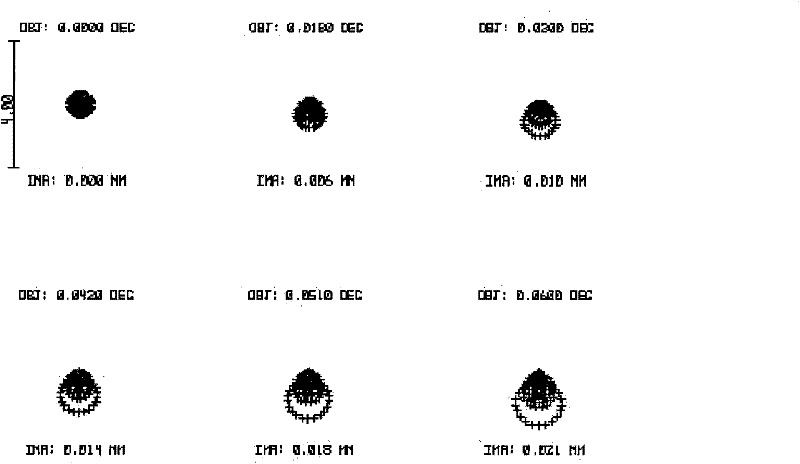
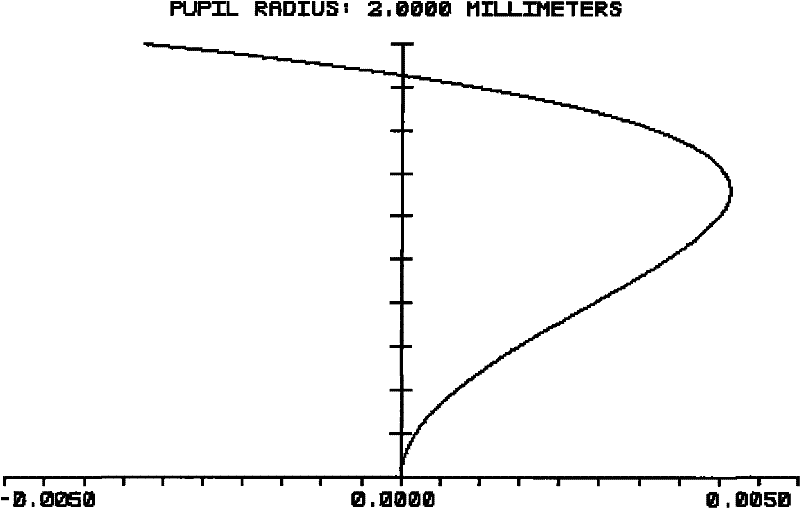
[0032] Among them, Φ 入 is the maximum incident light diameter allowed by the beam expander system, that is: the maximum beam of the incident laser beam that the beam expander system can receive is directly 4mm; β is the beam expansion multiple, that is: the beam expander system is the diameter of the incident laser beam After the beam is expanded by 5 times, it is still a beam of parallel light, which can solve the requirement of shaping the ultraviolet laser beam and expanding the diameter of the laser beam to improve the imaging quality; λ is the wavelength, that is, the incident light is an ultraviolet laser with a wavelength of 355nm.

[0033] Surface S

Curvature R(mm)

Surface spacing d(mm)

MaterialNd / Vd

1

62

2

1.46 / 68

2

10

100

3

0

3.5

1.46 / 68

4

-62

[0034] The range of parameters implemented by this pat...


PUM


Abstract

The invention provides a laser beam-expanding system, which comprises a first lens and a second lens which are positioned in the incident direction of a beam and are arranged in turn, wherein the first lens is a crescent-type negative lens; the curved surface of the first lens backs onto the incident direction of a ray and bends; the second lens is a plano-convex positive lens; and the whole beam-expanding system can perform bean expansion on the diameter of an incident laser beam by 5 times and then emit the beam as a parallel beam. Through the two lenses which have focal power assigned in a'negative-positive' form and are arranged in turn, the laser beam-expanding system can perform bean expansion on the diameter of an incident laser beam by 5 times and then emit the beam still as a parallel ray. As the focal length of the negative first lens is short and hardly affects aberration, the bean expansion multiple of the beam-expanding system is not big, so one positive lens is enough to undertake the quality of expanded emitted beams. Therefore, the system ensures shaping need, achieves the best imaging quality, and also ensures minimum overall dimensions. The beam-expanding systemhas the advantages of balanced ideal image quality and small volume of the whole lens.

Description

【Technical field】 [0001] The invention relates to a fixed-magnification beam expander system applied to ultraviolet lasers. 【Background technique】 [0002] In the process of laser processing, the energy of the laser at the focal point is usually required to be very concentrated, so as to ensure the energy density of the focal point during laser processing, so that the laser can work effectively and improve the working efficiency of the laser. However, how to increase the focused energy density of the laser during work Woolen cloth? Generally by getting as small a focal point as possible. [0003] According to the diffraction limit theory: the divergence angle θ of the laser and the diameter of the light waist d 0 The relationship is Among them, for the use of a certain laser, the wavelength λ of the laser is certain, so the divergence angle θ of the laser is related to the diameter of the light waist d 0 The product of is a constant. The diameter of the laser beam outp...

Claims


Application Information

Patent Timeline
Patent Type & Authority Patents(China)
IPC IPC(8): G02B27/09
Inventor 高云峰李家英周朝明
Owner HANS LASER TECH IND GRP CO LTD
Why Eureka
Try Eureka