Edge node for connecting Ethernet and optical burst switching network

A technology of optical burst switching and edge nodes, which is applied in data switching networks, digital transmission systems, electrical components, etc., and can solve problems such as inability to improve congestion at edge nodes

Inactive Publication Date: 2010-06-30
ZHEJIANG UNIV OF TECH
View PDF0 Cites 7 Cited by
  • Summary
  • Abstract
  • Description
  • Claims
  • Application Information

AI Technical Summary

Problems solved by technology

[0004] In order to overcome the shortcomings of the existing technology that cannot improve the congestion at the edge node when the network data transmission is bursty, the present invention provides a network that can connect Ethernet and optical burst switching network, and realize the burstiness between Ethernet frame and OBS. Full-duplex conversion between sending packets, in the case of bursty network data transmission, early detection of congestion can be performed, which can improve the congestion at the edge node and is used to connect the edge of Ethernet and optical burst switching network Nodes and Implementation Methods

Method used


Image

  • Edge node for connecting Ethernet and optical burst switching network
  • Edge node for connecting Ethernet and optical burst switching network
  • Edge node for connecting Ethernet and optical burst switching network

Examples


Embodiment 1

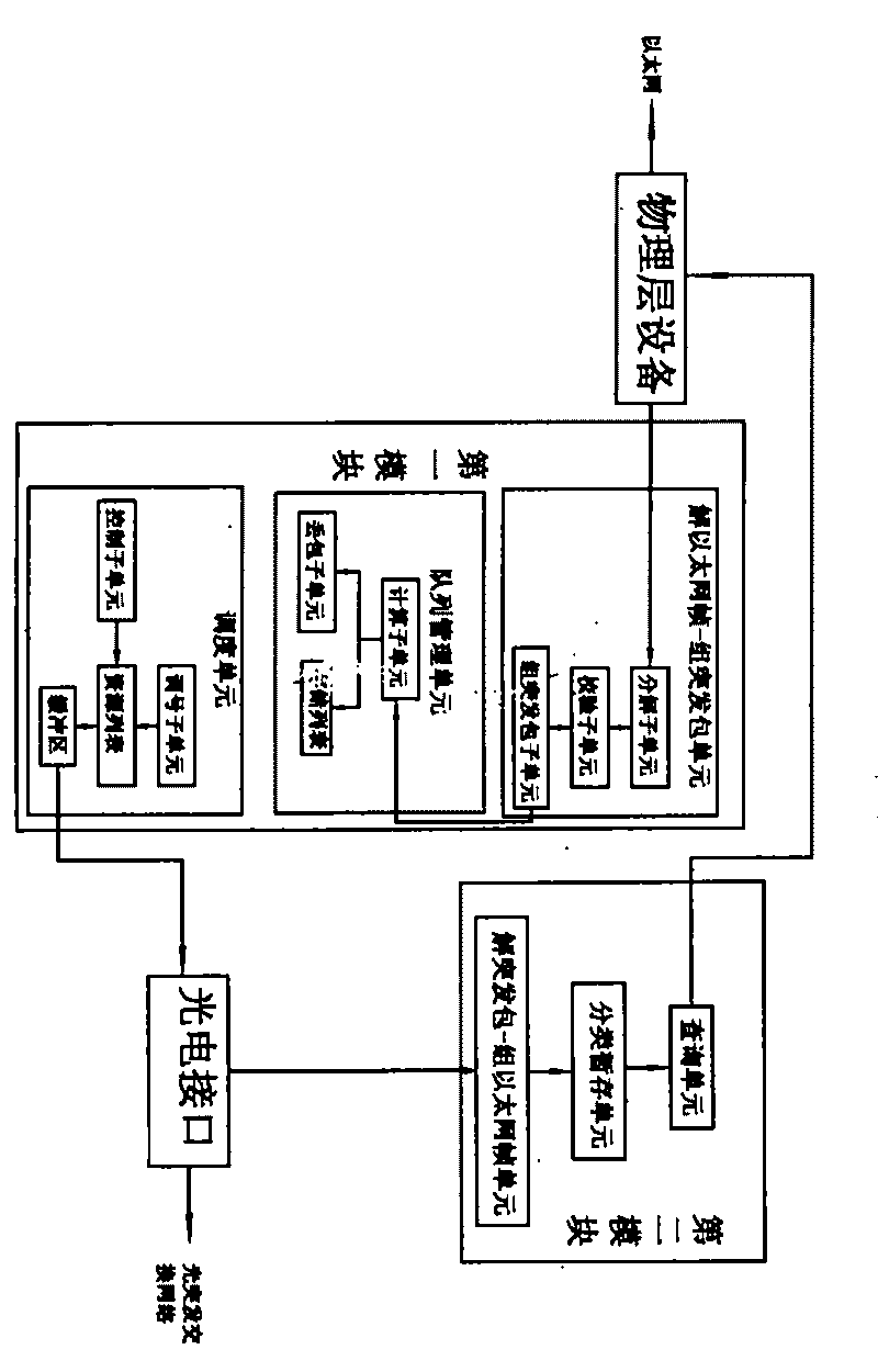
[0062] Refer to attached figure 1

[0063] The edge node used to connect the Ethernet and the optical burst switching network, including: a physical layer device that realizes the physical layer access of the Ethernet frame, and transmits data from the Ethernet to the first switching module and the optical burst switching network Transmitting data from the optical burst switching network to the second switching module of the Ethernet;

[0064] Described first switch module comprises: analyze ethernet frame to obtain its destination address, and this ethernet frame is assembled into BCP burst packet and BDP burst packet solution ethernet frame-group burst packet unit, to burst Early detection of packet congestion, reduce the sending rate before the router buffer queue overflows, and store each burst packet according to its destination address, and search for an idle control channel, and use the wavelength corresponding to the idle control channel to send the BCP burst send th...

Embodiment 2

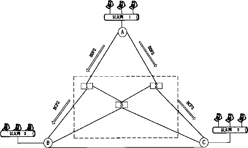
[0110] Combining examples and Figure 2-9 , to further illustrate the present invention:

[0111] Such as figure 2 As shown, A, B, and C represent three edge nodes of the optical burst switching network; 1, 2, and 3 represent three core nodes of the optical burst switching network; BCP2 represents a BCP burst packet whose destination address is 2; BDP2 Indicates the BDP burst packet with the destination address 2; BCP3 indicates the BCP burst packet with the destination address 3; BDP3 indicates the BDP burst packet with the destination address 3.

[0112] Suppose there are Ethernet frames Y1, Y2~Y6 that need to be transmitted from Ethernet 1 to Ethernet 2 or Ethernet 3; the source addresses of Y1, Y2, and Y4 are users 1, 2, and 4 of Ethernet 1, and the destination addresses are Ethernet The source addresses of users 1, 2, and 4 of 2; the source addresses of Y3, Y5, and Y6 are users 3, 5, and 6 of Ethernet 1, and the destination addresses are users 3, 5, and 6 of Ethernet 3...


PUM


Abstract

The invention relates to an edge node for connecting an Ethernet and an optical burst switching network, which comprises physical layer equipment, a first switching module and a second switching module, wherein the first switching module comprises an Ethernet frame analyzing and burst packet grouping unit, a queue managing unit and a scheduling unit; the second switching module comprises a burst packet analyzing and Ethernet grouping unit, a category temporary-storing unit and an inquiry unit. The realizing method for the edge node comprises the following steps of: judging the flowing direction of data; if the data is sent to the burst packet switching network from the Ethernet, analyzing the Ethernet frame, and grouping the burst packets; storing each burst packet according to the destination addresses; finding an idle channel to send the burst packets; if the data is sent to the Ethernet from the burst switching network, analyzing the burst packets and extracting the Ethernet frame; respectively storing the Ethernet frames according to the destination addresses; finding an idle physical interface to send the Ethernet frame, waiting for the next data, and repeating the steps. The invention has the advantages of full duplex switching and blockage improvement.

Description

technical field [0001] The invention relates to an edge node structure in an optical burst switching (OBS) network, and mainly relates to an edge node between an optical burst switching network and an Ethernet (Ethernet). technical background [0002] In the communication network, except for the user line, the traditional cables have been replaced by optical fibers. Optical fiber has the characteristics of low transmission loss and high transmission bandwidth, and the application of wavelength division multiplexing (WDM) technology in the transmission network makes the transmission bandwidth of the network backbone up to several Tbits per second. However, the switching capability of the current network nodes is insufficient, which has become a bottleneck restricting the development of the current network. In order to increase the switching capacity and reduce the switching cost, it is imperative to improve the traditional optical switching technology. Optical Burst Switchi...

Claims


Application Information

Patent Timeline
Patent Type & Authority Applications(China)
IPC IPC(8): H04L12/56H04L1/00H04L12/931
Inventor 乐孜纯付明磊卞燕如张明
Owner ZHEJIANG UNIV OF TECH
Why Eureka
Try Eureka