Air conditioner and cleaner extension nozzle using same

A technology for air-conditioning devices and vacuum cleaners, which can be used in air-conditioning systems, applications, household heating, etc., and can solve problems such as structures that cannot be called very convenient

Active Publication Date: 2013-07-31
DAIKIN IND LTD
View PDF1 Cites 0 Cited by
  • Summary
  • Abstract
  • Description
  • Claims
  • Application Information

AI Technical Summary

Problems solved by technology

[0006] However, in the air conditioner configured as described above, although the dust collected on the air filter can be removed and stored in the dust storage container without bothering the user's hands, the dust stored in the dust storage container is recovered and stored in the dust storage container. When the dust is collected, the operator must also go to the dust storage container installed near the air-conditioning device in the ceiling to recover the dust from the dust storage container
[0007] That is, in the above-mentioned structure, when recovering the dust removed from the air filter, the operator must climb to the vicinity of the ceiling, so it cannot be called a very convenient structure.

Method used


Image

  • Air conditioner and cleaner extension nozzle using same
  • Air conditioner and cleaner extension nozzle using same
  • Air conditioner and cleaner extension nozzle using same

Examples


no. 1 approach

[0210] The present embodiment is an air conditioner 10 including a dust collection structure for collecting dust removed from the air filter 40 . In this air conditioner 10, the indoor unit 13 is installed in the ceiling of the indoor space. In addition, the structure of the air-conditioning apparatus 10 which concerns on this embodiment is demonstrated first below, and the structure of the indoor unit 13 and a dust recovery structure are demonstrated sequentially next.

[0211]

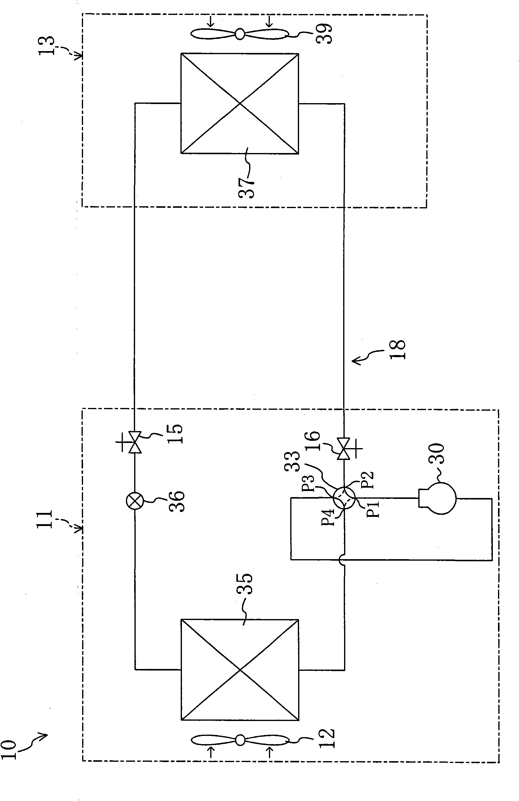
[0212] Such as figure 1 As shown, the air conditioner 10 includes an outdoor unit 11 and an indoor unit 13 . The outdoor unit 11 is provided with a compressor 30 , an outdoor heat exchanger 35 , an expansion valve 36 , a four-way reversing valve 33 and an outdoor fan 12 . The indoor unit 13 is provided with an indoor heat exchanger 37 and an indoor fan 39 .

[0213] In the outdoor unit 11 , the discharge side of the compressor 30 is connected to the first valve port P1 of the four-way reversing ...

no. 2 approach

[0305] Next, a second embodiment of the present invention will be described based on FIGS. 17 and 18 . In addition, in this embodiment, as shown in FIGS. 17 and 18 , the other end of the recovery duct 77 is located on the suction side of the indoor fan 39 , and the indoor side of the suction nozzle connection portion 131 connected to the other end is covered by the suction grille 29 . Unlike the first embodiment, the same parts are given the same symbols, and the different parts will be described below.

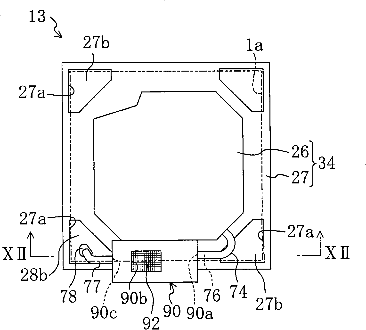
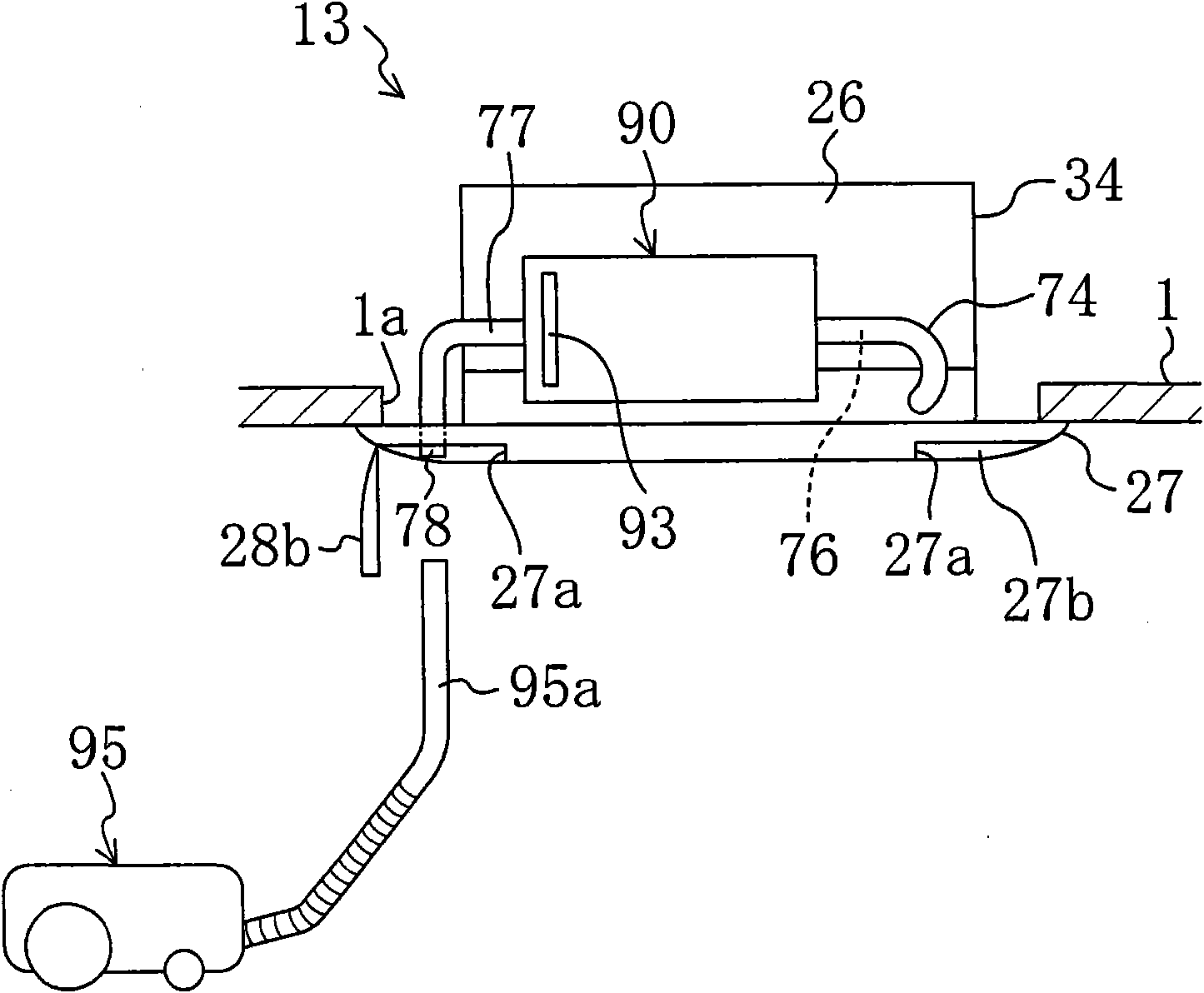
[0306] That is, as shown in FIG. 17 , one end of the recovery duct 77 connected to the recovery duct opening 90 c of the dust collection box 90 is provided so that the other end thereof is located in the suction port 22 in the case main body 26 .

[0307] The other end of the recovery duct 77 is connected to a nozzle connection portion 131 having the same configuration as the nozzle connection portion 78 of the first embodiment. In this embodiment, the nozzle connection port...

no. 3 approach

[0313] Next, a third embodiment of the present invention will be described based on FIG. 19 . Also, the present embodiment, as shown in FIG. 19 , differs from the second embodiment only in the point where the suction grille 29 is provided with the nozzle connection portion 151 and the like and the structure of the suction nozzle connection portion 151 . The same symbols are assigned to the same parts, and the different parts will be described below.

[0314] Specifically, like the second embodiment, this embodiment also has one end connected to the other end of the recovery duct 77 on the recovery duct opening 90 c of the dust collection box 90 and located at the suction port 22 of the case main body 26 . In addition, the suction nozzle connecting portion 151 connected to the other end of the recovery duct 77 is provided on the suction grille 29 covering the indoor side of the suction port 22 as shown in FIG. 19 .

[0315] Specifically, a box-shaped cover member 141 is provid...


PUM


Abstract

Dust collection structure for collecting the dust removed from an air filter of an indoor unit has been devised to reduce user's labor in collecting the dust as much as possible. An indoor unit (13) includes, in a casing (34), an indoor heat exchanger (37), an indoor fan (39) for sucking air from inside of a room, and blowing the air to the inside of the room, and an air filter (40) arranged on an inlet side of the indoor fan (39). The dust trapped on the air filter (40) is removed by the dust removing means (50), and is contained in the dust containing part (60). A nozzle connector (78) for arranging a nozzle (95a) of a cleaner (95) at a predetermined position where suction of the contained dust is allowed is provided at a downstream outlet of a dust collection path (77) as a transfer path for transferring the dust in collecting the contained dust.

Description

technical field [0001] The present invention relates to a dust collection structure for collecting dust removed from an air filter in an indoor unit of an air conditioner. Background technique [0002] Conventionally, an indoor unit of an air conditioner provided with an air filter at an air intake port is known in which a dust removal mechanism for removing dust trapped on the air filter is provided. In this air conditioner, since the dust storage container for storing the removed dust is installed in the indoor unit, when the user wants to throw away the dust in the dust storage container, he must remove the cover (grid, etc.) from the indoor unit. , take out the dust container. [0003] In this regard, for example, as disclosed in Patent Document 1, it is conceivable to arrange the dust container outside the housing body of the indoor unit in such a manner that only the dust container can be removed, and to remove the air from the dust collector by the wind flow. The du...

Claims


Application Information

Patent Timeline
Patent Type & Authority Patents(China)
IPC IPC(8): F24F13/28F24F1/0067F24F1/0073
CPCF24F1/0007F24F2013/0616B08B9/035B01D2279/50B01D46/0065F24F2001/0037F24F13/28F24F2003/1639F24F1/0047F24F8/90F24F1/0067F24F1/0073B01D46/681F24F1/0071F24F13/20F24F13/08F24F8/10B01D46/682
Inventor 坂下朗彦
Owner DAIKIN IND LTD
Why Eureka
Try Eureka