Method for treating flue gas of dyeing and finishing setter

A processing method and a technology of a setting machine, applied in separation methods, chemical instruments and methods, and separation of dispersed particles, etc., can solve pungent odors, pollute the factory area and the surrounding atmospheric environment, and affect the normal life and health of enterprise employees and surrounding residents. Health and other issues, to achieve the effect of saving energy and reducing the amount of sewage

Inactive Publication Date: 2010-07-07
NINGBO UNIV
View PDF0 Cites 35 Cited by
  • Summary
  • Abstract
  • Description
  • Claims
  • Application Information

AI Technical Summary

Problems solved by technology

[0004] The flue gas of the setting machine is white or light blue smoke, mixed with stench and pungent smell, which seriously pollutes the factory area and the surrounding atmospheric environment. Billowing white smoke not

Method used


Image

  • Method for treating flue gas of dyeing and finishing setter
  • Method for treating flue gas of dyeing and finishing setter
  • Method for treating flue gas of dyeing and finishing setter

Examples


Embodiment 1

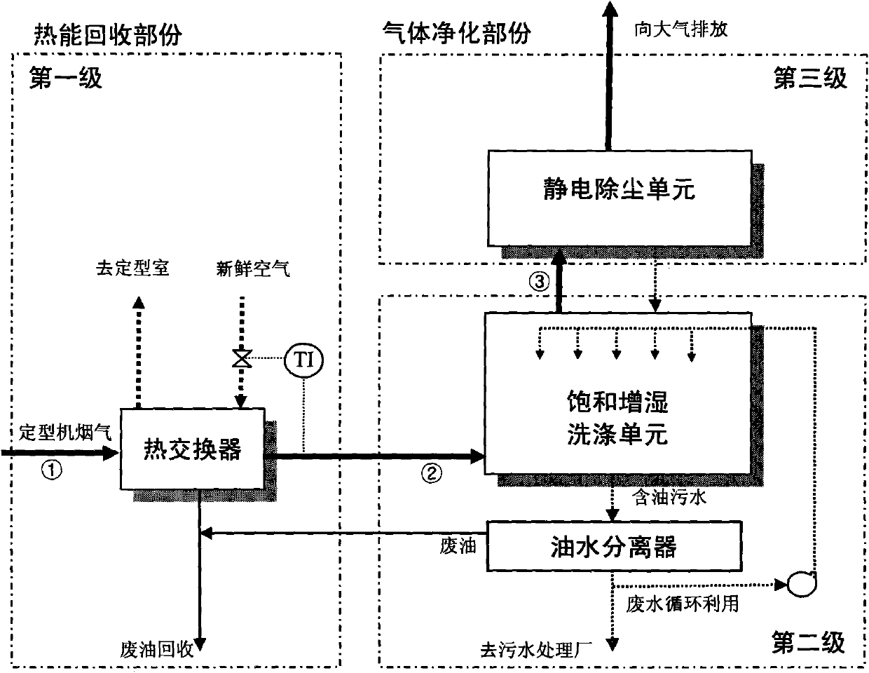
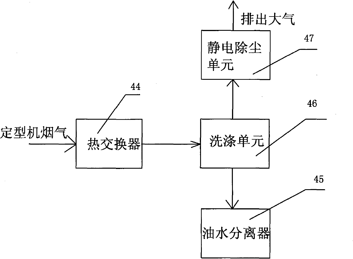
[0036] Embodiment one: if figure 1 As shown, a treatment method for flue gas of a dyeing and finishing machine, the rear end of the setting machine is provided with a heat exchanger 44, a washing unit 46, an oil-water separator 45 and an electrostatic dust removal unit 47, and the setting machine passes through the heat exchanger 44 and the washing unit 46 is communicated, the washing unit 46 is communicated with the oil-water separator 45, and the washing unit 46 is communicated with the electrostatic precipitator unit 47, and the specific steps include:

[0037] (1) The flue gas discharged from the sizing machine is input into the heat exchanger 44, and the flue gas exchanges heat with the air flowing through the heat exchanger 44 countercurrently, and the air after the heat exchange through the heat exchanger 44 is input to the external heating device, and the The air heated by the external heating device is then input into the setting room of the setting machine as a dryin...

Embodiment 2

[0045] Embodiment two: if Figure 8 and Figure 9 As shown, the other parts are the same as the first embodiment, the difference is that the electrostatic precipitator unit 47 and the washing unit 46 are integrated to form a wet electrostatic precipitator tower body 43 .

[0046] The electrostatic dust removal unit is arranged above the washing unit, and the specific structure is as follows: it includes a tower body 23, the lower end of the tower body 23 is provided with a flue gas inlet 24 and a sewage outlet 25, and the upper end of the tower body 23 is provided with an exhaust port 26, and the tower body 23 A spray pipe 27 and a filter packing layer 28 are arranged inside, the filter plastic layer 28 is arranged on the filter plastic layer support 37, the filter packing layer 28 is located below the spray pipe 27, and a guide ring 29 is arranged above the smoke inlet 24 , the end of the diversion ring 29 is provided with a knuckle hypotenuse 30, and the inner fixing of the...


PUM


Abstract

The invention discloses a method for treating flue gas of a dyeing and finishing setter. The rear end of the setter is provided with a heat exchanger, a washing unit, an oil-water separator and an electrostatic dedusting unit. In the method, (1) the counterflow heat exchange is carried out between the flue gas of the setter and the air by the heat exchanger, the waste heat is recovered, and the energy is saved; (2) the flue gas treated by the heat exchanger enters from the bottom of the washing unit and is sprayed and washed by the spraying liquid in the washing unit, and the flue gas is in counterflow contact with the spraying liquid, so as to remove most soot grains with the grain diameter being more than 1mum; and (3) the flue gas treated by the washing unit is dedusted by the wet-type electrostatic dedusting unit, most soot grains with grain diameter being less than 1mum are attached by electrons with high density, the charged grains move to the wall of a condensation pipe directionally and are collected and captured by the wall of the pipe, and the liquid film on the inner wall of the condensation pipe is updated continuously, thereby achieving the self-cleaning function of the inner wall of the condensation pipe.

Description

technical field [0001] The invention relates to a treatment method for industrial high-temperature oily and wet fume, in particular to a treatment method for fume from a dyeing and finishing machine. Background technique [0002] Chemical fiber textiles often need to add a variety of oily textile chemical auxiliaries in the upstream weaving and dyeing processes. In the finishing and setting process of printing and dyeing factories, a large amount of high-temperature oily and humid fumes will be generated when heated and dried by the setting machine. [0003] Usually, the temperature of the flue gas of the setting machine is generally in the range of 160-190°C, and the exhaust volume is 50-210Nm for each setting machine 3 / min; The pollutants in the flue gas mainly include weaving oil, spinning oil, organic solvents for refining and cleaning, dyes and dyeing auxiliaries. The particle concentration is 70-230mg / m 3 , in which the concentration of viscous particles is 25-120mg...

Claims


Application Information

Patent Timeline
IPC IPC(8): B01D50/00
Inventor 高华生陈和平朱建林
Owner NINGBO UNIV
Why Eureka
Try Eureka