Twin-translation-rotation partial decoupling parallel mechanism

A rotating part and two-translation technology, which is applied in manipulators, program-controlled manipulators, manufacturing tools, etc., can solve problems such as complex structure of two-translation-rotation parallel mechanisms, phase coupling between input and output, and complex spatial positions of kinematic pairs. Achieve the effect of easy calibration, small error accumulation and compact structure

Inactive Publication Date: 2010-07-07
SHANDONG UNIV AT WEIHAI
View PDF7 Cites 30 Cited by
  • Summary
  • Abstract
  • Description
  • Claims
  • Application Information

AI Technical Summary

Problems solved by technology

[0003] The technical problem solved by the present invention is to provide a high rigidity, asymmetrical structure, and a rotational solution Coupled, easy to control, good dynamic performance Two translational one rotating part decoupled parallel mechanism

Method used


Image

  • Twin-translation-rotation partial decoupling parallel mechanism
  • Twin-translation-rotation partial decoupling parallel mechanism
  • Twin-translation-rotation partial decoupling parallel mechanism

Examples


Embodiment 1

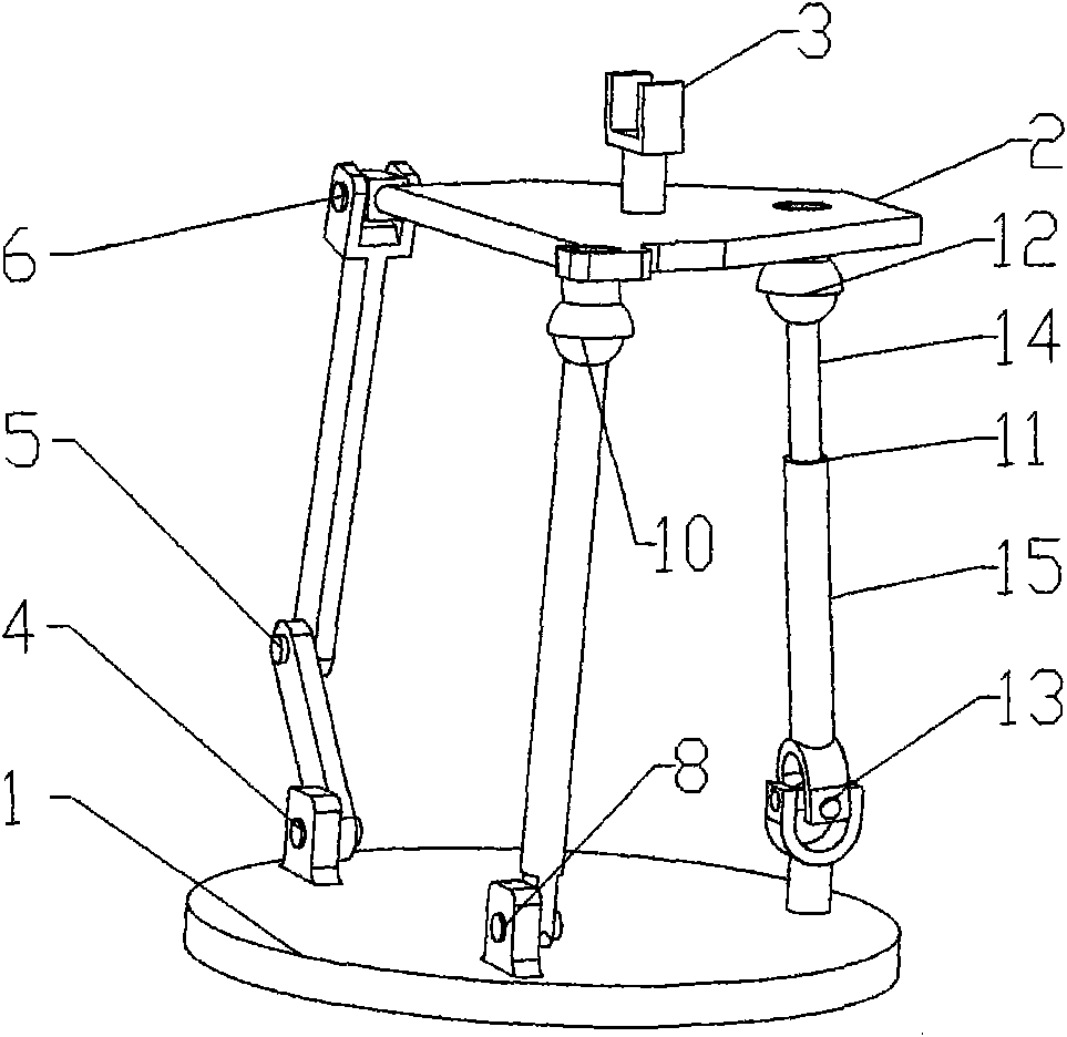
[0015] Such as figure 1 The shown two-translation-rotation part decouples the parallel mechanism, the fixed platform 1 is provided with a movable platform 2 , and the movable platform 2 is provided with an end effector 3 . The fixed platform 1 is connected to the moving platform through three different branches, the first branch is provided with an intermediate kinematic pair, and the middle kinematic pair is the rotating pair 5; the kinematic pair directly connected with the fixed platform 1 in the first branch is the rotating pair 4 ; The kinematic pair directly connected with the moving platform 2 in the first branch is a universal hinge 6 . The kinematic pair directly connected with the fixed platform 1 in the second branch is the revolving joint 8 ; the kinematic pair directly connected with the moving platform 2 in the second branch is the ball pair 10 . The third branch is composed of a branch chain with six degrees of freedom in space, and the third branch is provided...

Embodiment 2

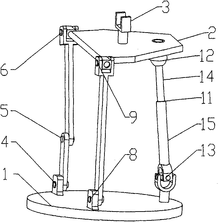
[0017] Such as figure 2 The shown two-translation-rotation part decouples the parallel mechanism, and the kinematic pair directly connected with the moving platform 2 in the first branch is the universal hinge 6 . The kinematic pair directly connected with the moving platform 2 in the second branch is a universal hinge 9 . Other structures are the same as those in Embodiment 1, and will not be repeated here.

Embodiment 3

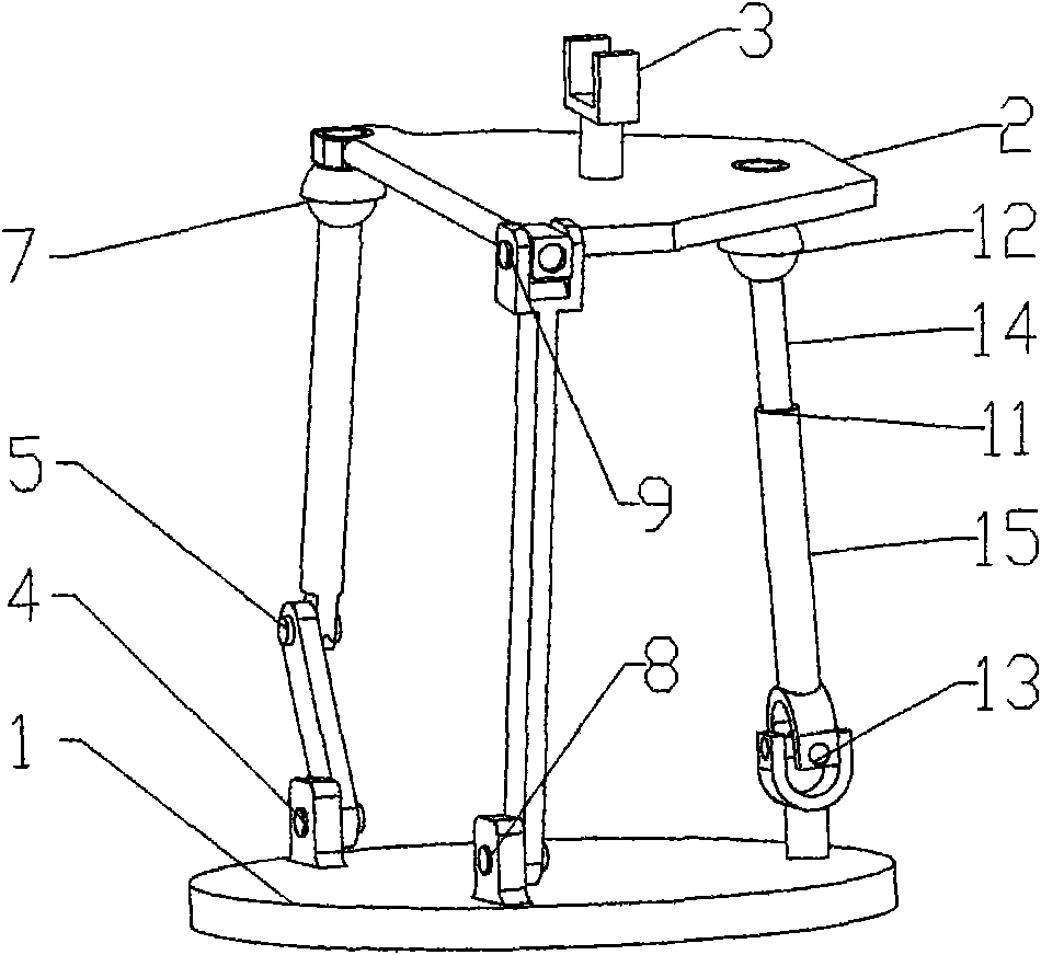
[0019] Such as image 3 The shown two-translation-rotation part decouples the parallel mechanism, and the kinematic pair directly connected with the moving platform 2 in the first branch is the ball pair 7 . The kinematic pair directly connected with the moving platform 2 in the second branch is a universal hinge 9 . Other structures are the same as those in Embodiment 1, and will not be repeated here.


PUM


Abstract

The invention relates to a twin-translation-rotation partial decoupling parallel mechanism, relating to a three-degree-freedom parallel mechanism in the field of industrial robots. A movable platform is arranged above a fixed platform; a tail-end actuator is arranged above the movable platform; the fixed platform is connected with the movable platform through three alien branches; a first branch is provided with a rotary pair, and a movable pair of the first branch connected with the fixed platform is a rotary pair; a movable pair in the first branch connected with the movable platform is a universal joint or a ball pair; a movable pair in the second branch connected with the fixed platform is a rotary pair; a movable pair in the second branch connected with the movable platform is a universal joint or a ball pair; a third branch is formed by a branch chain with six degrees of freedom and is provided with a movable pair; a movable pair of the third branch connected with the fixed platform is a universal joint; a movable pair of the third branch connected with the movable platform is a ball pair; and the movable pair, the ball pair and the universal joint in the third branch are connected into UPS branch chain. The invention is suitable for machine tools, robots, and the like.

Description

technical field [0001] The invention belongs to the three-degree-of-freedom parallel mechanism in the field of industrial robots, specifically a two-translation-rotation part decoupling parallel mechanism. Background technique [0002] The parallel mechanism refers to the mechanism that is connected by two or more branches between the moving platform and the fixed platform, the mechanism has two or more degrees of freedom, and is driven in parallel. Parallel mechanisms have been widely used in many technical fields in recent years because of their advantages such as high rigidity, strong bearing capacity, small error accumulation, good dynamic performance, and compact structure. The early parallel mechanism is usually a Stewart parallel mechanism with 6 degrees of freedom. The moving platform of this mechanism is connected with the fixed platform by six branches. There are two spherical joints at both ends of each branch, and a moving pair in the middle. The driving pair pu...

Claims


Application Information

Patent Timeline
Patent Type & Authority Applications(China)
IPC IPC(8): B25J9/08
Inventor 陈原杜清府
Owner SHANDONG UNIV AT WEIHAI
Why Eureka
Try Eureka