

Centrifugal fan blade
A centrifugal fan and blade technology, applied in the field of power machinery, can solve the problems of large separation and dissipation area, impact loss, etc., and achieve the effects of high pressure rise and efficiency, performance improvement, and reduction of airflow separation and energy loss
- Summary
- Abstract
- Description
- Claims
- Application Information
AI Technical Summary
Problems solved by technology
Method used
Image

Examples
Embodiment Construction
[0026] The embodiments of the present invention are described in detail below. This embodiment is implemented on the premise of the technical solution of the present invention, and detailed implementation methods and specific operating procedures are provided, but the protection scope of the present invention is not limited to the following implementation example.
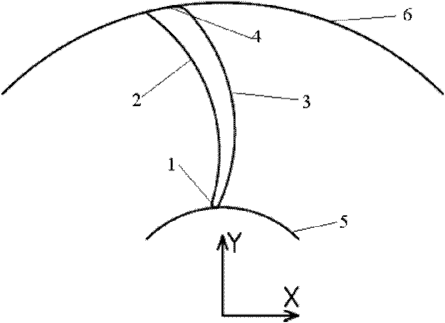
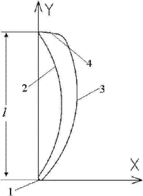
[0027] Such as figure 1 and figure 2 As shown, the blade of this embodiment is located in the fan, and the blade includes: a leading edge 1, a pressure surface 2, a suction surface 3 and a trailing edge 4, wherein: the leading edge 1 is tangent to the inner diameter 5 of the fan, and the trailing edge 4 Located on the outer diameter 6 of the fan, one end of the pressure surface 2 and one end of the suction surface 3 are respectively connected to the two ends of the leading edge 1, and the other end of the pressure surface 2 and the other end of the suction surface 3 are respectively connected to the two ends of t...
PUM
 Abstract
Description
Claims
Application Information