
Ultrasonic liquid level meter owning gas sound speed real-time correction

An ultrasonic and speed of sound technology, applied in the field of liquid level measurement, can solve the problems of high cost of use, difficult to meet the requirements of precision, and complex measuring devices, to simplify the difficulty of on-site installation and instrument maintenance, solve the problem of accuracy stability, and reduce costs. Effect

Inactive Publication Date: 2010-07-07
PHOTIME INSTR GUANGZHOU
View PDF0 Cites 27 Cited by
  • Summary
  • Abstract
  • Description
  • Claims
  • Application Information

AI Technical Summary

Problems solved by technology

When the medium is close to an ideal gas (such as air) and the gas temperature is precisely known, it is possible to achieve a relatively high accuracy, but the actual system to be measured in the industrial control process is often more complicated, and the gas temperature is often a variable parameter. Bit measurement is difficult to achieve high accuracy
For non-ideal gas environments, pressure data must also be introduced during calculation, which makes the measurement device more complicated and the accuracy is more difficult to meet the requirements
[0006]At present, most of the commonly used ultrasonic liquid level gauges use a single ultrasonic probe, which requires regular calibration or on-site calibration, and the actual use cost is relatively high
In addition, because the use of a single ultrasonic probe cannot use advanced digital signal processing techniques such as correlation algorithms, in applications with poor signal-to-noise ratios, such as measuring multi-phase liquid levels and strongly attenuating gas media, it will cause inaccurate liquid level measurement. Stablize

Method used


Image

  • Ultrasonic liquid level meter owning gas sound speed real-time correction
  • Ultrasonic liquid level meter owning gas sound speed real-time correction
  • Ultrasonic liquid level meter owning gas sound speed real-time correction

Examples


Embodiment 1

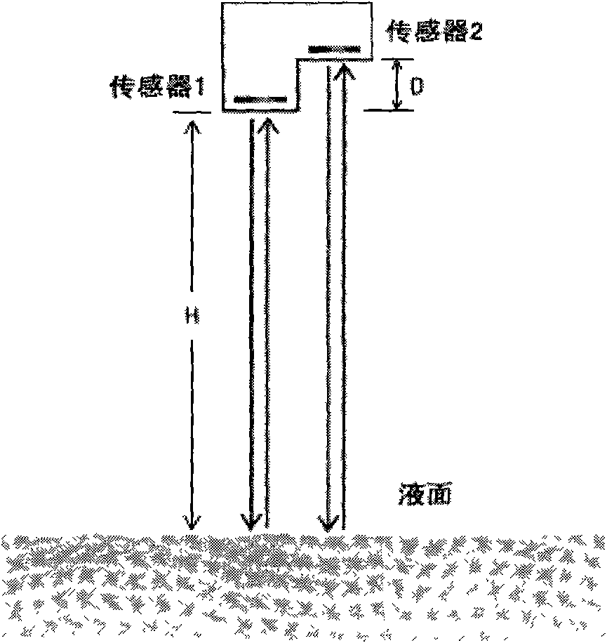
[0050] Such as figure 1 As shown, two ultrasonic sensors are used, and a fixed height difference D is staggered between them. Assuming that the gas sound velocity C and the liquid level height H are unknown quantities, the time-of-flight T1 of the sound wave of the sensor 1 in the gas and the time of flight of the sensor 2 The flight time T2 of the sound wave in the gas, according to the relationship between the flight time flight distance and the speed of sound, the following equations can be obtained:

[0051] T1=2*H / C

[0052] T2=(2*H+2*D) / C

[0053] Time difference between two beams of sound waves:

[0054] DT=T2-T1=2*D / C

[0055] This gives the speed of sound and the height of the liquid level:

[0056] C=2*D / DT

[0057] H=C*T1 / 2

[0058] If two ultrasonic sensors transmit signals at the same time, DT can be directly obtained by correlating the two received signals. This method is much more accurate than the method using the difference between T1 and T2, and is less...

Embodiment 2

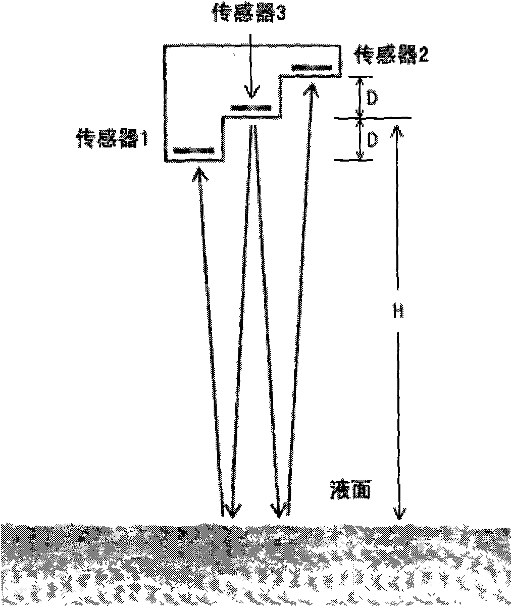
[0070] Such as figure 2 As shown, three ultrasonic sensors are used, one ultrasonic transmitting sensor and two receiving sensors. Each of the sensors 1 to 3 is staggered by a fixed height difference D, assuming that the gas sound velocity C and the liquid level height H are unknown quantities, and the sound wave flight time T1 from sensor 3 to sensor 1 and the sound wave from sensor 3 to sensor 2 are measured The flight time T2, according to the relationship between the flight time flight distance and the speed of sound, the following equations can be obtained:

[0071] T1=(2*H-2*D) / C

[0072] T2=(2*H+2*D) / C

[0073] Time difference between two beams of sound waves:

[0074] DT=T2-T1=4*D / C

[0075] This gives the speed of sound and the height of the liquid level:

[0076] C=4*D / DT

[0077] H=C*(T1+T2) / 2

[0078] The source of the two received signals using a fixed ultrasonic transmitting sensor is exactly the same, so that it can be obtained directly through correlati...


PUM


Abstract

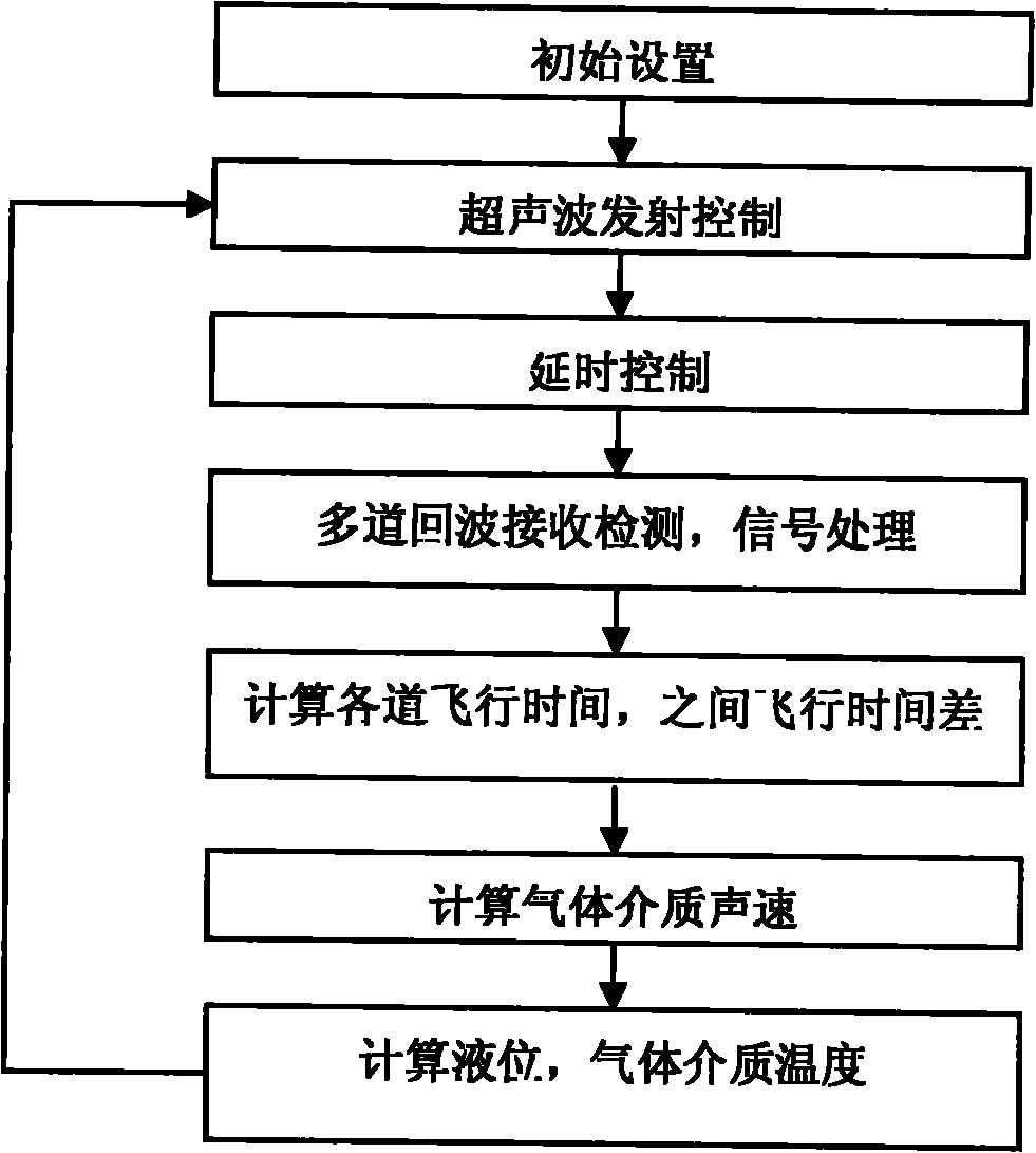
The present invention relates to a liquid level measuring method. A plurality of ultrasonic sensors above the liquid level is used. A fixed known height difference exists among every sensor for respectively measuring the round-trip flying time that sound wave sent by every ultrasonic sensor passing through the liquid level is reflected into gas, and then, the flying time difference of every sound wave is calculated. The sound speed of gas media is calculated by comparing the height differences to the time differences. Finally, the sound speed multiplies the flying time of the sound wave to obtain the height of liquid level which needs to be measured. The liquid level measuring method is realized by a special measuring device. The special measuring device comprises a measuring probe and an electronic device, wherein the measuring probe is composed of two or more ultrasonic sensors. The present invention has the advantages of that the height of the liquid level can be exactly measured in real time without the effect of the gas media; the precision stability is high; and the on-site correction and the maintenance of the special measuring device are convenient.

Description

technical field [0001] The invention relates to a method for measuring liquid level and its measuring device, in particular, a method for measuring liquid level by using multi-beam ultrasonic waves and its measuring device. Background technique [0002] At present, ultrasonic liquid level gauges are widely used in industrial control. Compared with other measurement methods, they are safe and radiation-free, easy to install, and have a long service life. The commonly used ultrasonic liquid level measurement technology has two ways of placing the sensor in the liquid and placing the sensor in the gas medium on the liquid surface. [0003] The method of placing the ultrasonic sensor in the liquid can easily achieve higher accuracy, but the measuring device will be affected by the deposition of liquid residue and oil, which will be affected by corrosion, and it is inconvenient to overhaul. The method of placing the ultrasonic sensor in the gas medium on the liquid surface is co...

Claims


Application Information

Patent Timeline
Patent Type & Authority Applications(China)
IPC IPC(8): G01F23/296G01K11/24G01H5/00
Inventor 刘风华
Owner PHOTIME INSTR GUANGZHOU
Learn More