
Full effect scanning laser range finder based on semi-ring reflector

A two-dimensional laser and mirror technology, applied in the field of laser rangefinders, can solve problems such as inability to perform measurement, and achieve the effects of improving measurement efficiency, simple driving mode, and low cost

Inactive Publication Date: 2012-09-05
BEIHANG UNIV
View PDF0 Cites 0 Cited by
  • Summary
  • Abstract
  • Description
  • Claims
  • Application Information

AI Technical Summary

Problems solved by technology

In the optical path of analyzing this structure, the mirror surface of the rotating plane mirror 3 is a plane mirror at an angle of 45° to the horizontal plane, and the distance of 180° of the horizontal plane in front can be measured through the directional and uniform rotation of the plane mirror, but when the plane mirror rotates to the rear 180° , the outgoing light will be incident on the support frame 6 and cannot be measured
It takes 13ms for each rotation of the rotating plane mirror 3, only half of the time is in effective measurement, and the measurement efficiency is only half

Method used


Image

  • Full effect scanning laser range finder based on semi-ring reflector
  • Full effect scanning laser range finder based on semi-ring reflector
  • Full effect scanning laser range finder based on semi-ring reflector

Examples


Embodiment Construction

[0027] The present invention will be further described in detail below in conjunction with the accompanying drawings.

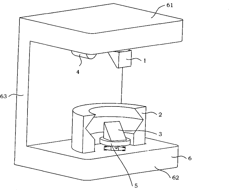
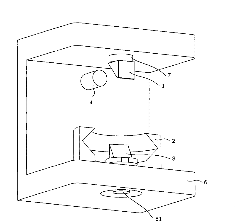
[0028] see figure 1 , Figure 1A As shown, a kind of full-effect two-dimensional laser rangefinder based on the near half-ring mirror of the present invention, the optical path part of the laser rangefinder includes a laser transmitter 4, a laser receiver 7, a beam splitter 1, a half-ring Mirror 2, rotating flat mirror 3, rotating assembly 5 and support frame 6.

[0029] In the present invention, the laser emitter 4 is used for emitting laser light 1A, and the central wavelength of the laser light 1A is 1550 nm.

[0030] In the present invention, the laser receiver 7 is used to receive the reflected light transmitted by the beam splitter 1 (ie, the second target return light 1E).

[0031] In the present invention, the beam splitter 1 is used to reflect the laser light 1A on the one hand, and to transmit the received return light on the other hand. The LB...


PUM


Abstract

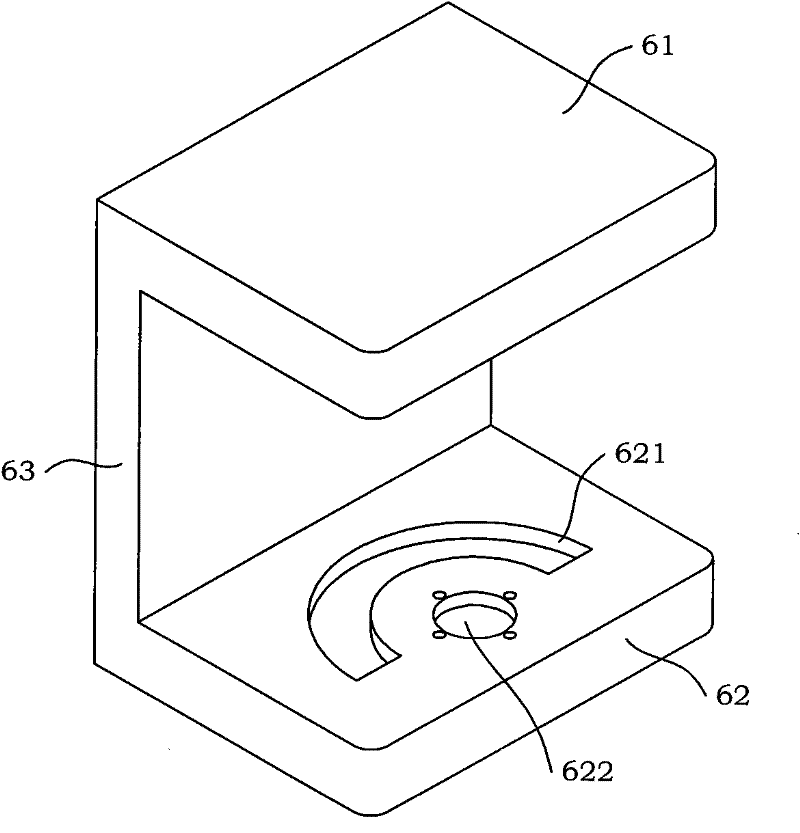
The invention discloses a full effect scanning laser range finder based on a semi-ring reflector. The light path of the laser range finder comprises a laser transmitter, a laser receiver, a spectroscope, a semi-ring reflector, a rotating plane mirror, a runner assembly and a support frame, wherein a blind hole A below the upper plate of the support frame is internally provided with the laser receiver, and the end face of the laser receiver is provided with the spectroscope; a semi-ring locating slot above the lower plate of the support frame is provided with a locating ring of the semi-ring reflector, a counter bore is internally provided with a motor connecting plate, a DC servo motor shell is arranged on the motor connecting plate, and the output shaft of the DC servo motor passes through the through hole of the counter bore and then is fixed on a connecting column of a turntable; the turntable is provided with the rotating plane mirror; and a blind hole B on the side plate of the support frame is internally provided with the laser transmitter. In the light path structure of the laser range finder of the invention, no matter the rotating plane mirror faces an object to be testedor is opposite to the object to be tested, effective measurement on the whole course can be obtained after the rotating plane mirror is turned in a full cycle, and the measuring efficiency is doubled; and with the improvement on the light path, the laser range finder enables the measuring method to be improved.

Description

technical field [0001] The present invention relates to a laser rangefinder, more particularly, to a full-effect two-dimensional laser rangefinder based on a half-ring reflector. Background technique [0002] Laser rangefinders have a series of advantages such as high measurement accuracy, good collimation, and strong anti-interference ability, and have been widely used in various measurement industries. Laser ranging can be divided into two types: pulse type and phase type. Pulse laser ranging is to measure the distance of the measured target by measuring the time difference between transmitting and receiving laser pulse signals. The measurement formula is L=ct / 2, L is the measurement distance, c is the speed of light, and t is the round-trip time of the ranging signal . Distance measurement is realized by counting the number of high-frequency counting pulses. [0003] see Figure 5A As shown, the optical path of the two-dimensional laser range finder model LMS291 produc...

Claims


Application Information

Patent Timeline
Patent Type & Authority Patents(China)
IPC IPC(8): G01S17/08
Inventor 陈伟海范海洲刘敬猛王建华高铭辰
Owner BEIHANG UNIV
Learn More