Automatic automobile clock correction system and correction method thereof
An automatic correction and correction method technology, which is applied in the field of accurate correction of automobile clocks, can solve problems affecting the accuracy of the clock, affecting the normal use of the car owner, and time display deviations, so as to ensure accuracy, complete automation of the correction method, and step-by-step simple effect
- Summary
- Abstract
- Description
- Claims
- Application Information
AI Technical Summary
Problems solved by technology
Method used
Image

Examples
Embodiment 1
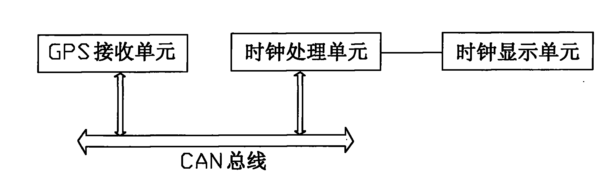
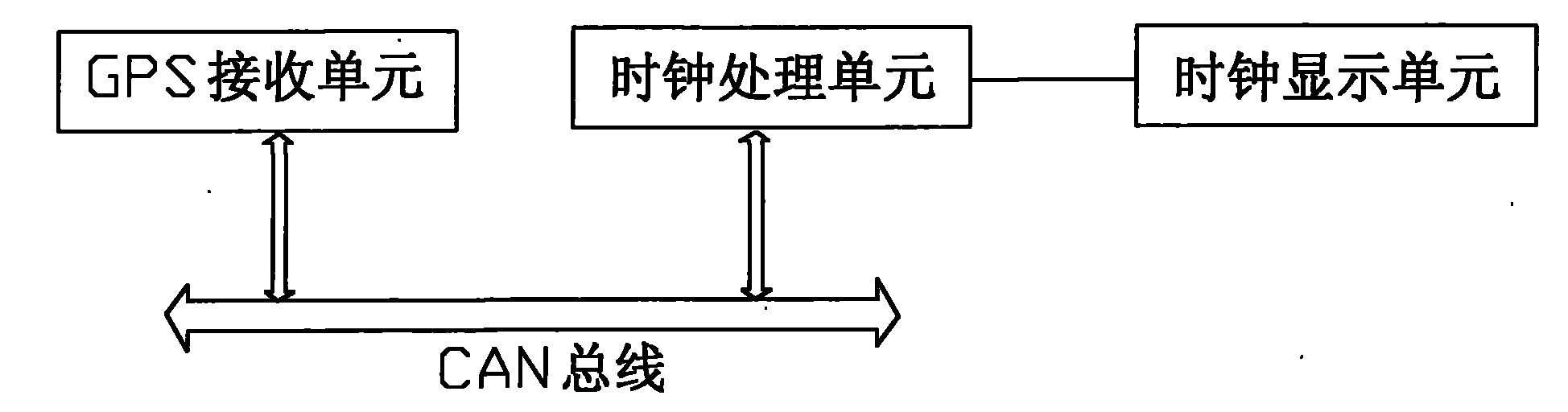
[0015] Such as figure 1 As shown, the automobile clock automatic correction system of this embodiment includes a clock processing unit and a clock display unit, the clock processing unit includes a clock signal generation circuit and a clock signal processing circuit, and the clock display unit receives and displays the clock signal sent by the clock processing unit clock signal, and the clock processing unit is connected to a GPS receiving unit through a CAN bus.
[0016] The correction method of the above-mentioned automobile clock automatic correction system includes the following steps: after the automobile is powered on, the clock processing unit uses the GPS receiving unit to receive the satellite clock synchronization signal, and corrects the local clock according to the synchronization signal. After the correction is completed, the clock processing unit Shield the satellite clock synchronization signal of the GPS receiving unit, use its built-in clock signal generation...
Embodiment 2
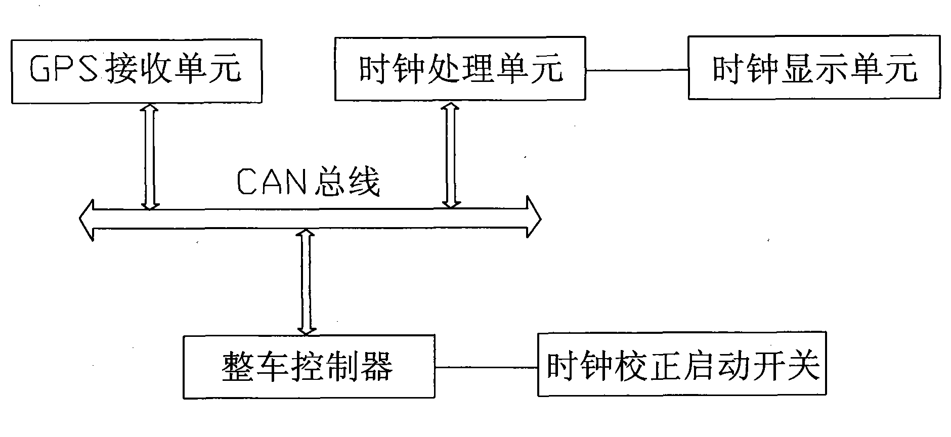
[0018] Such as figure 2 As shown, different from Embodiment 1, the clock processing unit of this embodiment is also connected to the vehicle body controller through the CAN bus, and the vehicle body controller is connected to a clock correction start switch.
[0019] The correction method of the above-mentioned automobile clock automatic correction system includes the following steps: after the automobile is powered on, the clock processing unit uses the GPS receiving unit to receive the satellite clock synchronization signal, and corrects the local clock according to the synchronization signal. After the correction is completed, the clock processing unit Shield the satellite clock synchronization signal of the GPS receiving unit, use its built-in clock signal generation circuit and clock signal processing circuit to time and generate a clock signal, and send the clock signal to the clock display unit for display; when the body controller receives the clock After correcting t...
PUM
 Abstract
Description
Claims
Application Information
 - Generate Ideas
- Intellectual Property
- Life Sciences
- Materials
- Tech Scout
- Unparalleled Data Quality
- Higher Quality Content
- 60% Fewer Hallucinations
Browse by: Latest US Patents, China's latest patents, Technical Efficacy Thesaurus, Application Domain, Technology Topic, Popular Technical Reports.
© 2025 PatSnap. All rights reserved.Legal|Privacy policy|Modern Slavery Act Transparency Statement|Sitemap|About US| Contact US: help@patsnap.com