
Identification key of radio-frequency antenna

A radio frequency antenna and key technology, applied to instruments, time registers, single input port/output port registers, etc., can solve problems such as leakage, and achieve the effects of reducing inconvenience, preventing detection, and preventing information leakage

Active Publication Date: 2010-07-07
SHANGHAI LIANGKE ELECTRONICS TECH
View PDF9 Cites 0 Cited by
  • Summary
  • Abstract
  • Description
  • Claims
  • Application Information

AI Technical Summary

Problems solved by technology

[0005] In view of the above-mentioned technical status, the present invention proposes a radio frequency antenna identification key, which effectively avoids the detection of information on the user's RFID by external detectors, and prevents security issues such as leakage of user information

Method used


Image

  • Identification key of radio-frequency antenna
  • Identification key of radio-frequency antenna
  • Identification key of radio-frequency antenna

Examples


Embodiment 1

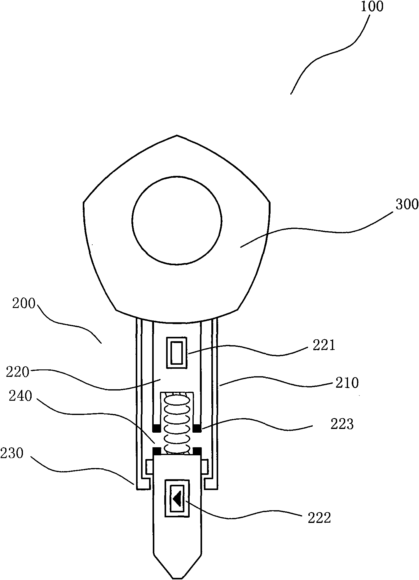
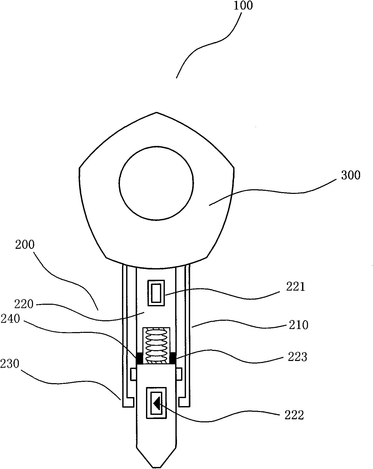
[0032] image 3 It is a structural schematic diagram of an embodiment of a radio frequency antenna identification key according to the present invention. In this embodiment, the pressure switch 240 is realized by setting it as an elastic sphere structure, and the structure includes:

[0033] The key shaft 200 is fixedly connected to the key handle 300 through the inner side. The key shaft 200 is provided with a key shaft inner core 210 and a locking layer 230 for locking the key shaft inner core 210 . The clamping layer 230 is provided with a raised limit structure to limit the position of the key shaft inner core 210 and prevent the key shaft inner core 210 from being stretched excessively. At the same time, the clamping layer 230 can also prevent the user from using When the radio frequency antenna recognizes that the key 100 is improper, the inner core 210 of the key shaft is separated from the key shaft 200 . Further, a radio frequency circuit 220 with a radio frequency ...

Embodiment 2

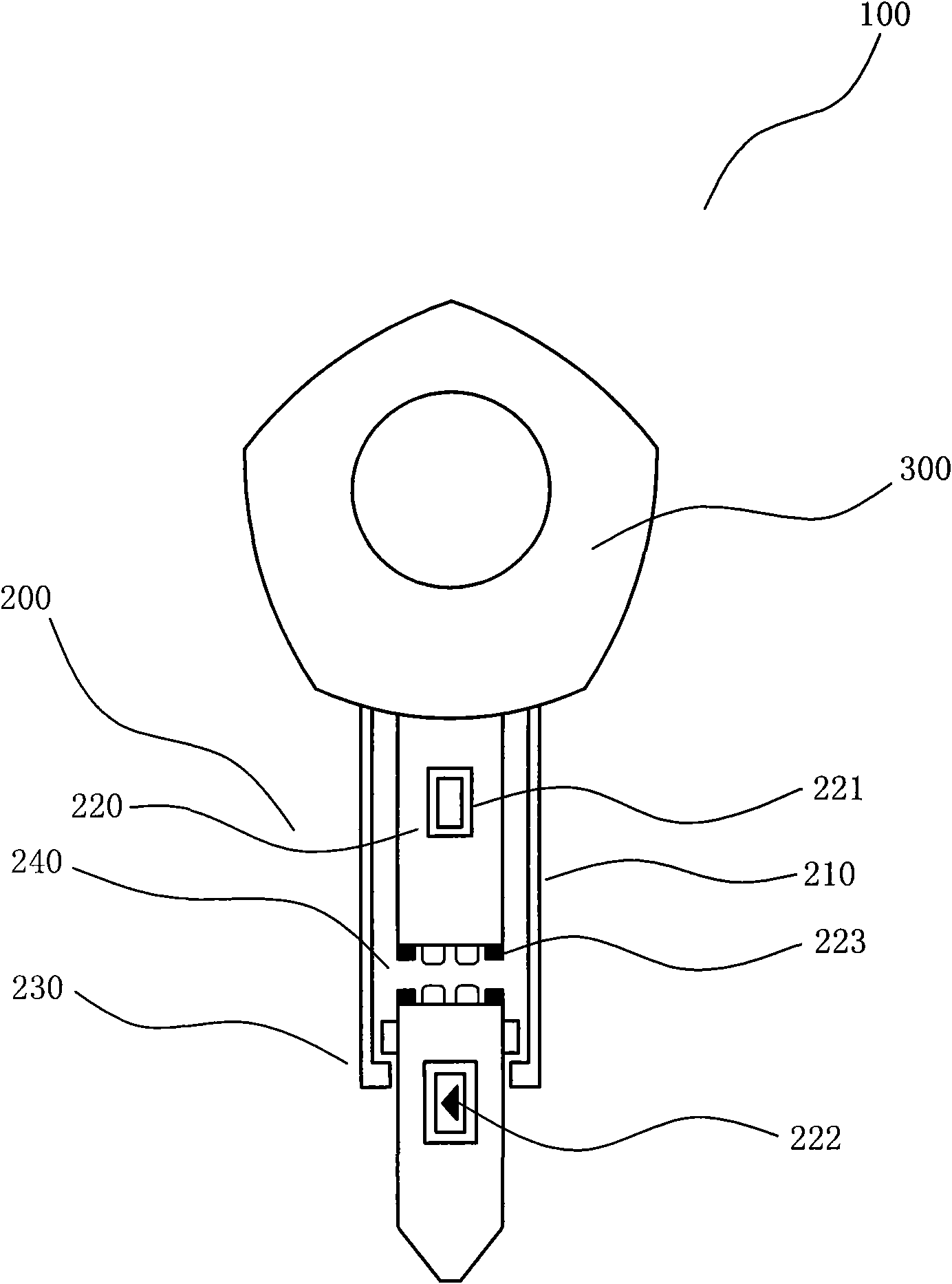
[0039] Figure 4 It is a structural schematic diagram of another embodiment of a radio frequency antenna identification key according to the present invention. In this embodiment, the pressure switch 240 is realized by a magnetic structure, and the magnetism of the external system 400 is set to "S" pole , the external magnetism at the end of the key shaft inner core 210 away from the key handle 300 is set as "S" pole. The structure includes:

[0040] The key shaft 200 is fixedly connected to the key handle 300 through the inner side. The key shaft 200 is provided with a key shaft inner core 210 and a locking layer 230 for locking the key shaft inner core 210 . The clamping layer 230 is provided with a raised limit structure to limit the position of the key shaft inner core 210 and prevent the key shaft inner core 210 from being stretched excessively. At the same time, the clamping layer 230 can also prevent the user from using When the radio frequency antenna recognizes that ...


PUM


Abstract

The invention provides an identification key of a radio-frequency antenna, belonging to the field of daily electronic equipment. A radio-frequency circuit is arranged in a main structure of the key; the circuit breakover part of the radio-frequency circuit comprises at least two components; and a pressure switch structure that can be used for controlling the breakover state of the radio-frequency circuit through the pressure is arranged between the components, thereby effectively avoiding the detection of an external detector for the information on a user RFID and preventing the information outleakage of a user and other safety problems. Meanwhile, with the adoption of the identification key of the radio-frequency antenna, the identification function of the radio-frequency antenna can be realized when the user comes into the room, so as to reduce the inconvenience caused by different inner disks of the key when in key bitting. A clamping layer arranged on the key can avoid the phenomenon that a key-bar inner disk is separated from a key bar due to the inappropriate usage of the identification key of the radio-frequency antenna.

Description

technical field [0001] The invention belongs to the field of daily electronic equipment. Background technique [0002] RFID is the abbreviation of Radio Frequency Identification, that is, radio frequency identification, commonly known as electronic tags. Write the data into the RFID chip. When the RFID chip is placed inside the magnetic field, the data stored in the RFID chip can be read and effectively identified through the corresponding data reading system. [0003] At present, due to the advantages of RFID technology that can work in harsh environments and is affordable, it is highly sought after by people and is widely used. However, the existing RFID devices do not protect their own data enough. As long as the RFID device is inside the corresponding magnetic field, it can be read by any data reading system, thus causing many inconveniences to people's life, study, entertainment, etc. safety factors. [0004] In order to improve the above problems, in recent years, m...

Claims


Application Information

Patent Timeline
IPC IPC(8): G07C9/00
Inventor 马宇尘
Owner SHANGHAI LIANGKE ELECTRONICS TECH
Learn More