Rotor supporting structure of high speed electric rotary machine and rotary machine

A technology of electric rotation and rotor support, applied in mechanical equipment, electric components, control of mechanical energy, etc., can solve the problems of low reliability, complex electric control and manufacturing, large friction loss of liquid sliding bearings, etc., to achieve stable and reliable operation of the system, The effect of reducing the relative rotational speed and improving the bearing life

Inactive Publication Date: 2010-07-07
何君 +2
View PDF0 Cites 6 Cited by
  • Summary
  • Abstract
  • Description
  • Claims
  • Application Information

AI Technical Summary

Problems solved by technology

At present, for the bearing design of this kind of high-power, high-speed motor, it is generally considered to adopt the active magnetic bearing support method of the mixed support of electromagnetic bearing and rolling bearing, but the electronic control and manufacture of this magnetic bearing are complicated, expensive and reliable. low, and cannot be commercialized at present; the use of liquid sliding bearings is limited to a certain extent due to the large friction loss when the motor rotates at high speed and the small bearing capacity of air sliding bearings; composite ceramic ball angular contact ball bearings are used as this large Power and high speed motor bearings have not been reported in China at present

Method used


Image

  • Rotor supporting structure of high speed electric rotary machine and rotary machine
  • Rotor supporting structure of high speed electric rotary machine and rotary machine
  • Rotor supporting structure of high speed electric rotary machine and rotary machine

Examples


Embodiment Construction

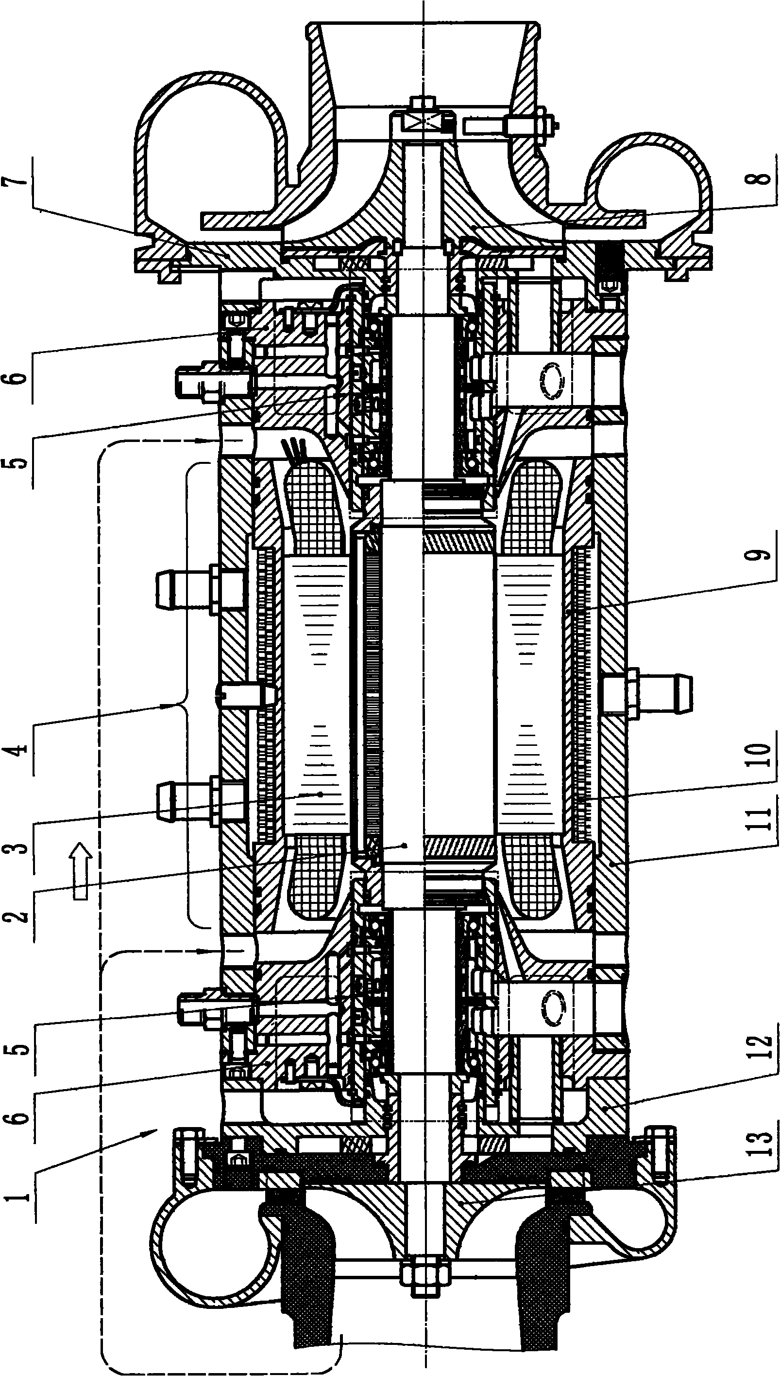
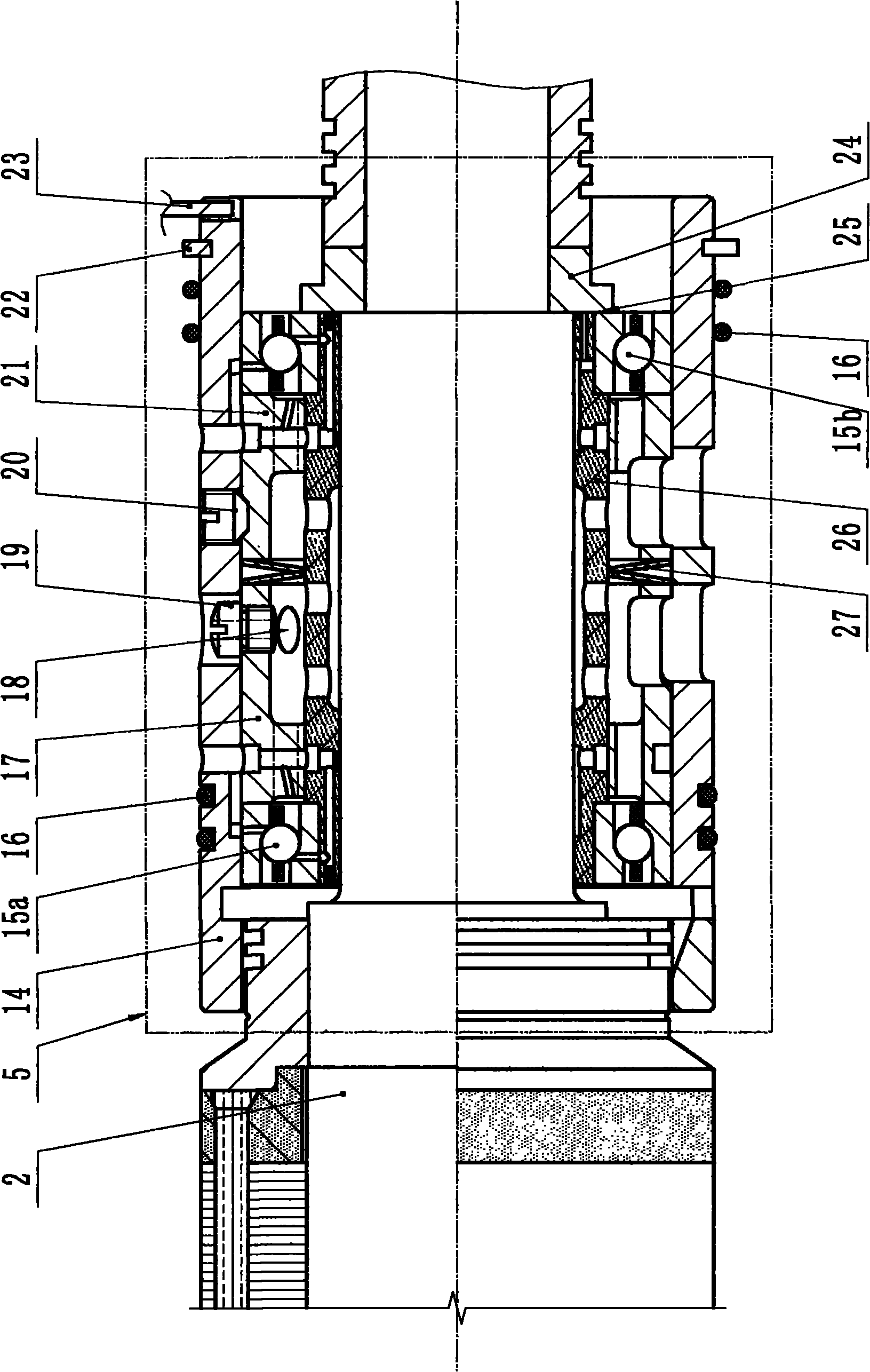
[0009] Specific embodiments of the present invention will be described below in conjunction with the accompanying drawings. figure 1 Shown is a front view of an air refrigerator 1 driven directly by an electric motor 4 comprising a semi-floating roller-slide double bearing 5 of the present invention. figure 1 Among them, the air refrigerator 1 includes an electric motor 4 in the middle thereof. The motor 4 includes a rotor 2 and a stator 3 . The opposite sides of the rotor 2 are semi-floating roller-sliding double bearings 5 ​​. The bearing seat 6 of the left end and the left water jacket cover 12 form the left cooling water jacket, and the bearing seat 6 of the right end and the right water jacket cover 7 form the right cooling water jacket. The stator casing 9 brazed with cooling fins 10 and the body 11 form the cooling water jacket of the stator 3 . The cooling impeller 13 and the compressor impeller 8 are fixed on the two shaft ends of the rotor 2 . Part of the cool ai...


PUM


Abstract

The invention discloses a rotor supporting structure of a high speed electric rotary machine. Two end parts of radical sliding bearings at journals of two ends of a rotor are sheathed with a pair of angular contact ball bearings, constant-pressure prestressing is adopted between the two ball bearings, the two balling bearings are embedded in a floating bush, and the outer side end of the floating bush is provided with a check ring and a stop dog to limit the floating bush from moving and rotating along the axial direction and enable the floating bush to be loaded in a bearing seat hole with a certain fit clearance to be in a semi-floating state, thus forming a semi-floating rolling-sliding double bearing. When the high power high speed electric rotary machine adopting the rotor supporting structure of the invention is arranged in a vehicle which runs high speed of above 60000r / min, due to the action of the semi-floating rolling-sliding double bearing, the system can be stably and reliably operated.

Description

technical field [0001] The present invention relates to a rotor support structure for high-speed electric rotating machines, in particular to rotor supports for air refrigerators, air compressors, etc. driven by large-capacity high-speed electric motors installed on vehicles, etc. Wherein the rotor rotates at a high speed of, for example, not less than tens of thousands of revolutions per minute. Background technique [0002] One of the main technical issues in the design of high-power, high-speed high-speed motors (20kw, above 60000 / min) is bearing design. At present, for the bearing design of this kind of high-power, high-speed motor, it is generally considered to adopt the active magnetic bearing support method of the mixed support of electromagnetic bearing and rolling bearing, but the electronic control and manufacture of this magnetic bearing are complicated, expensive and reliable. low, and cannot be commercialized at present; the use of liquid sliding bearings is li...

Claims


Application Information

Patent Timeline
Patent Type & Authority Applications(China)
IPC IPC(8): H02K7/08F04D29/056F04D29/063
Inventor 何君伍怀秋何应明
Owner 何君
Why Eureka
Try Eureka