Miniature fluid control device

a control device and fluid technology, applied in the direction of machines/engines, liquid fuel engines, positive displacement liquid engines, etc., can solve the problems of not being portable, unable to meet the miniaturization requirement of pneumatic devices, and being bulky in volume, so as to simplify the formation of the piezoelectric actuator of the present invention, and increase the thickness of the adhesive layer.

Active Publication Date: 2020-06-30
MICROJET TECH
View PDF21 Cites 0 Cited by
  • Summary
  • Abstract
  • Description
  • Claims
  • Application Information

AI Technical Summary

Benefits of technology

[0007]An object of the present invention provides a miniature fluid control device for a portable device or wearable device. Moreover, the regions of a metal plate corresponding to a suspension plate, an outer frame and at least one bracket of a piezoelectric actuator are etched at the same etch depth, and thus the integral structure of suspension plate, the outer frame and the at least one bracket is defined. Consequently, a second surface of the suspension plate, a second surface of the outer frame and a second surface of the bracket are coplanar with each other. In comparison with the conventional way using the multiple-step etching process to make the components in different depths, the process of forming the piezoelectric actuator of the present invention is simplified. The etched outer frame has a rough surface, which is beneficial to the adhesion of an adhesive layer inserted in the gap between the resonance plate and the outer frame. Moreover, since the thickness of the outer frame is less than the conventional one, the thickness of the adhesive layer can be increased, on the premise that a specified depth between the resonance plate and the outer frame should be maintained. The increase of the thickness of the adhesive layer can enhance the coating uniformity of the adhesive layer, reduce the assembling error of the suspension plate in the horizontal direction, and improve the efficiency of utilizing the kinetic energy of the suspension plate in the vertical direction. Moreover, the increase of the thickness of the adhesive layer can assist in absorbing vibration energy and reduce noise. Due to the slim, silent and power-saving benefits, the miniature fluid control device of the present invention is suitably used in the wearable device.
[0008]Another object of the present invention provides a miniature fluid control device with a piezoelectric actuator. A suspension plate of the piezoelectric actuator is a square plate with a bulge. After the fluid is introduced into an inlet of the gas inlet plate of a base, the fluid is guided to a central cavity through a convergence channel, and then the fluid is transferred to a compressible chamber between the resonance plate and the piezoelectric actuator through the central aperture of the resonance plate. Consequently, a pressure gradient is generated in the compressible chamber to facilitate the fluid to flow at a high speed. In the process, the flowrate of the fluid does not reduce and the pressure does not lose. The fluid is continuously discharged under pressure.

Problems solved by technology

However, due to the volume limitations of the motors and the pressure valves, the pneumatic devices or the pneumatic machines are bulky in volume.
In other words, the conventional pneumatic device fails to meet the miniaturization requirement and is not portable.
Moreover, during operations of the motor or the pressure valve, annoying noise is readily generated.
That is, the conventional pneumatic device is neither friendly nor comfortable to the user.
However, the conventional miniature fluid control device still has some drawbacks.
Under this circumstance, the rigidity of the overall structure is too strong that the suspension plate 121′ is unable to effectively absorb interference vibration energy during the vertical vibration of the piezoelectric actuator 12′.
In other words, the conventional miniature fluid control device 1′ loses unnecessarily energy and generates undesired noise, and the noise problem may result in the defectiveness of the products.

Method used


Image

  • Miniature fluid control device
  • Miniature fluid control device
  • Miniature fluid control device

Examples


Embodiment Construction

[0021]The present invention will now be described more specifically with reference to the following embodiments. It is to be noted that the following descriptions of preferred embodiments of this invention are presented herein for purpose of illustration and description only. It is not intended to be exhaustive or to be limited to the precise form disclosed.

[0022]The present invention provides a miniature fluid control device. The fluid control device can be used in many sectors such as pharmaceutical industries, energy industries computer techniques or printing industries for transporting fluids.

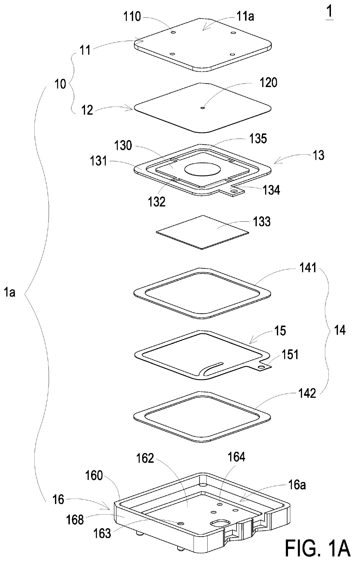
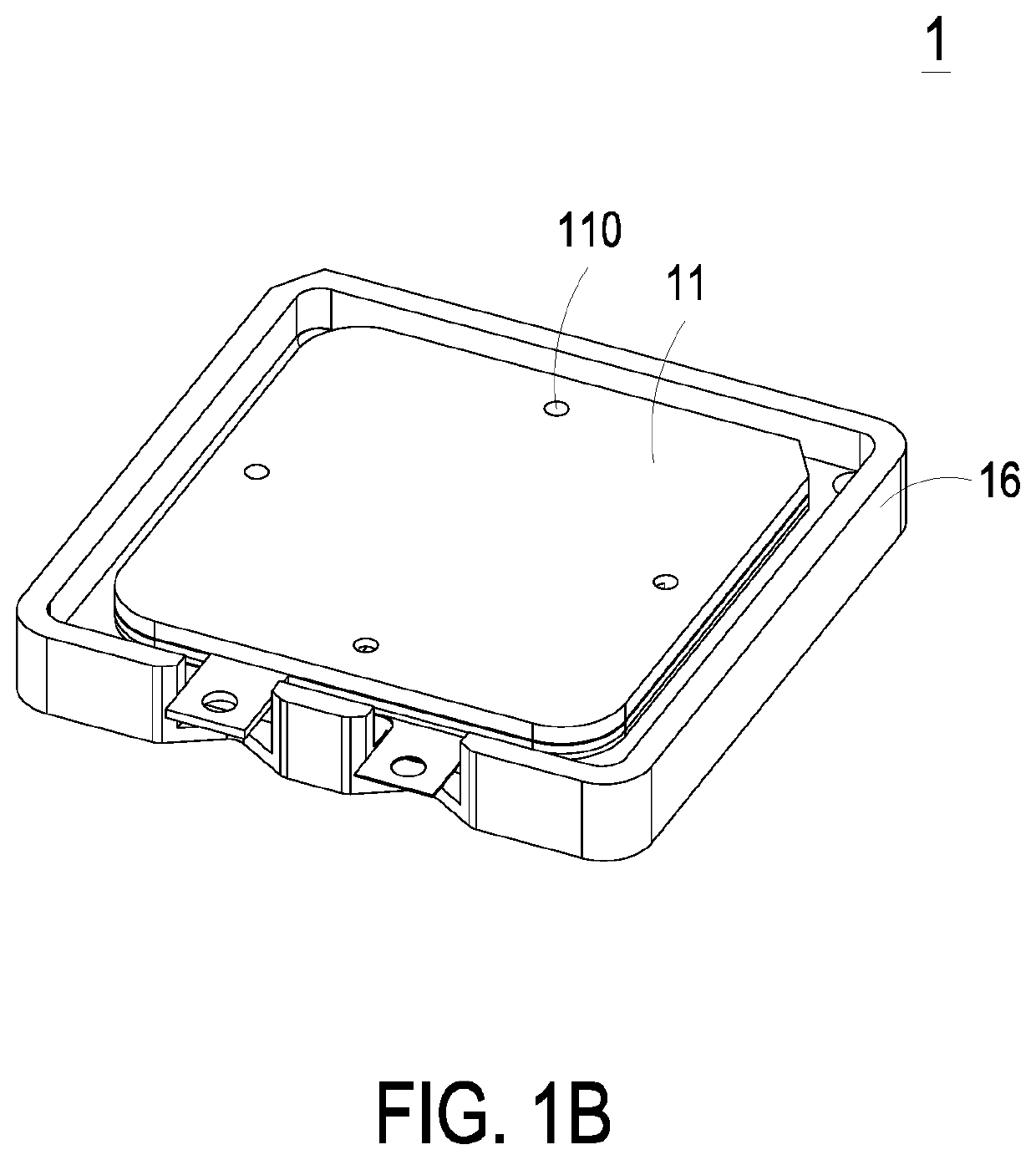
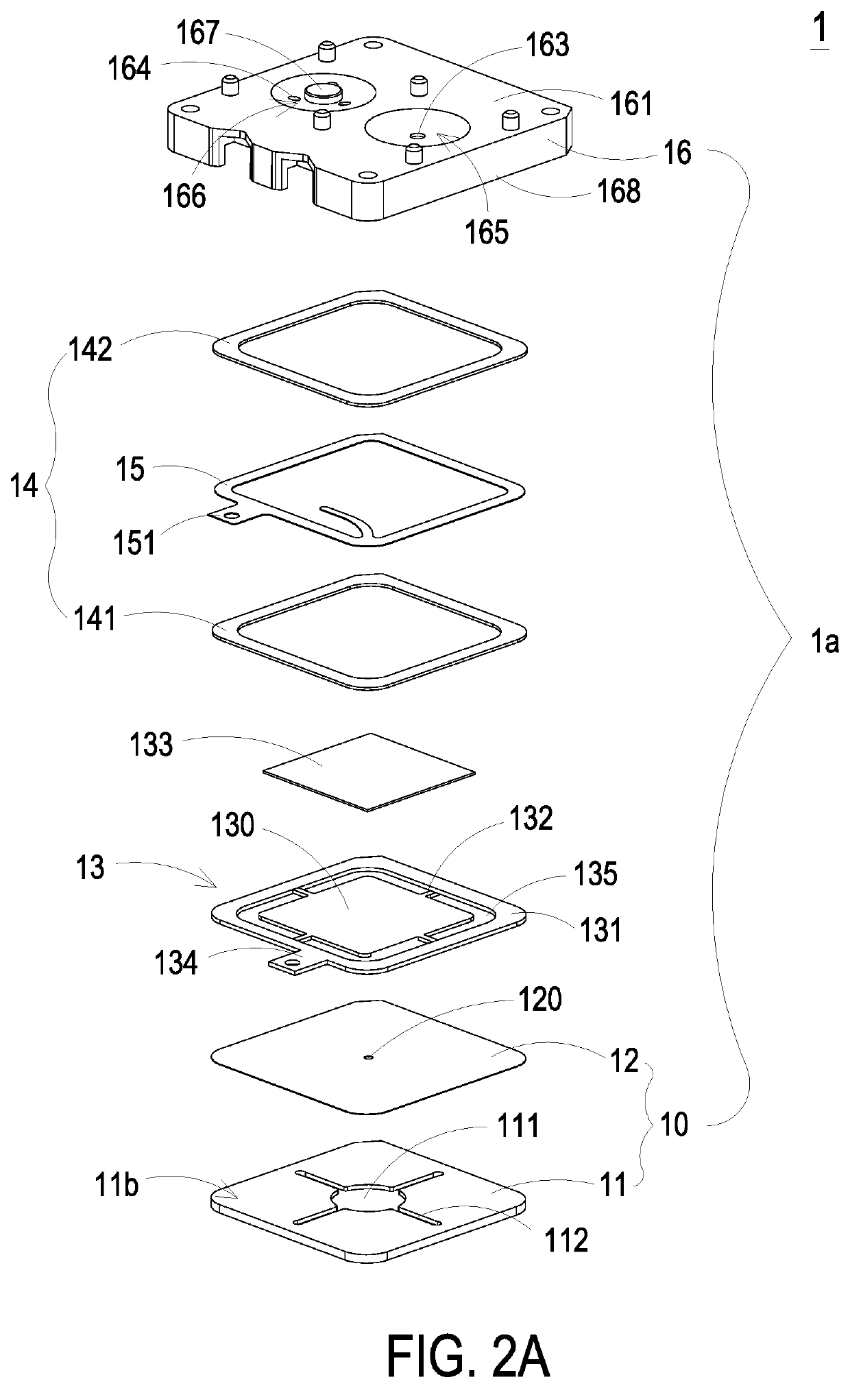
[0023]Please refer to FIGS. 1A, 1B, 2A, 2B and 5. FIG. 1A is a schematic exploded view illustrating a miniature fluid control device according to an embodiment of the present invention and taken along a first viewpoint. FIG. 1B is a schematic perspective view illustrating the assembled structure of the miniature fluid control device of FIG. 1A. FIG. 2A is a schematic exploded view illustrat...


PUM


Abstract

A miniature fluid control device includes a piezoelectric actuator, a gas collecting plate and a base. The piezoelectric actuator includes a suspension plate, an outer frame, at least one bracket and a piezoelectric ceramic plate. The suspension plate is a square plate. The outer frame is arranged around the suspension plate. A surface of the outer frame and a surface of the suspension plate are coplanar with each other. The gas collecting plate is a frame body with an accommodation space. The base includes a gas inlet plate and a resonance plate. The base is disposed within the accommodation space to seal the piezoelectric actuator. An adhesive layer is arranged between the second surface of the outer frame of the piezoelectric actuator and the resonance plate. Consequently, a depth of a compressible chamber between the piezoelectric actuator and the resonance plate is maintained.

Description

FIELD OF THE INVENTION[0001]The present invention relates to a miniature fluid control device, and more particularly to a slim and silent miniature fluid control device.BACKGROUND OF THE INVENTION[0002]With the advancement of science and technology, fluid control devices are widely used in many sectors such as pharmaceutical industries, computer techniques, printing industries or energy industries. Moreover, the fluid control devices are developed toward elaboration and miniaturization. The fluid control devices are important components that are used in for example micro pumps, micro atomizers, printheads or industrial printers for transporting fluid. Therefore, it is important to provide an improved structure of the fluid control device.[0003]For example, in the pharmaceutical industries, pneumatic devices or pneumatic machines use motors or pressure valves to transfer gases. However, due to the volume limitations of the motors and the pressure valves, the pneumatic devices or the ...

Claims


Application Information

Patent Timeline
Patent Type & Authority Patents(United States)
IPC IPC(8): F04B43/04F04B53/16F04B45/047F04B53/10
CPCF04B43/046F04B45/047F04B53/16F04B53/1067F04B39/12F04D33/00F05D2260/407
Inventor HAN, YUNG-LUNGHUANG, CHI-FENGCHEN, SHIH-CHANGLIAO, JIA-YULIAO, HUNG-HSINHUANG, CHE-WEICHEN, SHOU-HUNG
Owner MICROJET TECH
Why Eureka
Try Eureka