

Three-phase tri-level LLC resonant converter
A technology of resonant converter and three-phase transformer, which is applied in the direction of adjusting electrical variables, high-efficiency power electronic conversion, and converting DC power input to DC power output. It can solve the problems of performance degradation and high price of MOSFET devices, and achieve volume reduction. Effect
- Summary
- Abstract
- Description
- Claims
- Application Information
AI Technical Summary
Problems solved by technology
Method used
Image

Examples
specific Embodiment approach 1
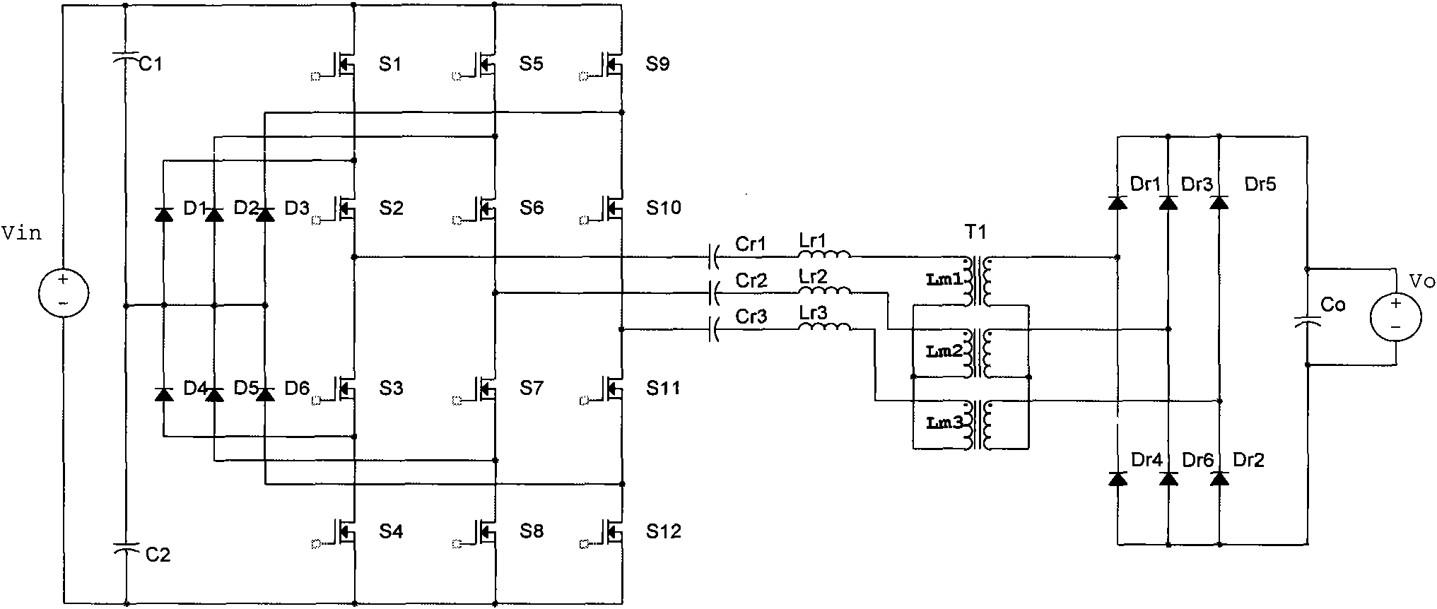
[0030] Such as figure 1 A three-phase three-level LLC resonant converter shown is a typical three-phase three-level LLC resonant converter. It includes a voltage dividing capacitor, an inverter, a clamp circuit, a resonant circuit, a three-phase transformer, a rectifier circuit, and a filter circuit.
[0031] The voltage dividing capacitor is two same polarity capacitors C1 and C2. The positive pole of the polar capacitor C1 is connected to the positive pole of the input voltage source Vin, and the negative pole of the polar capacitor C1 is connected to the positive pole of the polar capacitor C2 as the midpoint of the voltage dividing capacitor. , the negative pole of the polarized capacitor C2 is connected to the negative pole of the input voltage source Vin, and the input voltage source Vin is equally divided into two voltage sources whose voltage is only half of it.
[0032] The inverter consists of three three-level bridge arms connected in parallel to invert the DC vol...
specific Embodiment approach 2
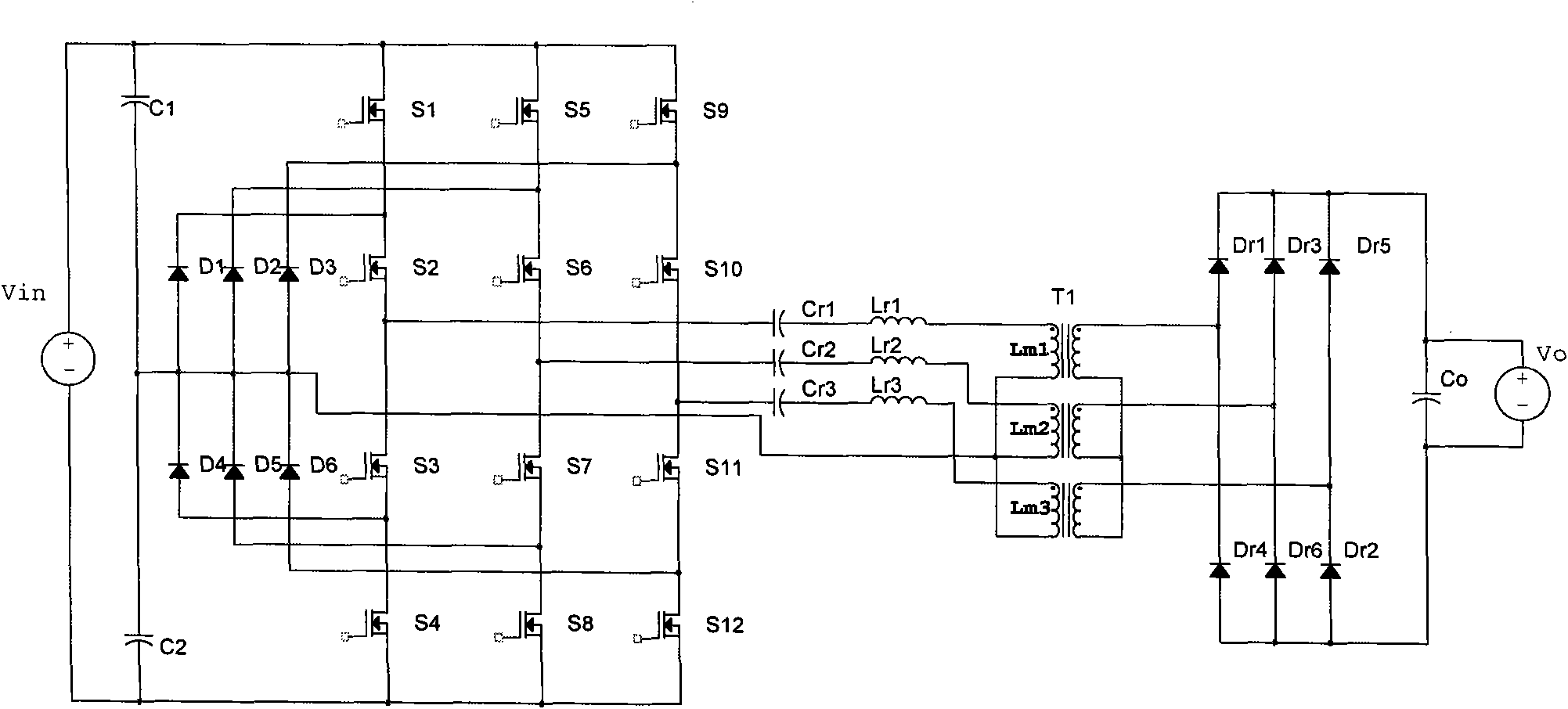
[0076] Such as figure 2 A three-phase three-level LLC resonant converter shown is a modified three-phase three-level LLC resonant converter. It also includes voltage dividing capacitors, inverters, clamping circuits, resonant circuits, three-phase transformers, rectifier circuits, and filter circuits. The difference from Embodiment 1 is that: the Y-shaped connection point of the primary winding of the three-phase transformer is connected to the middle point of the voltage dividing capacitor.
[0077] The second embodiment has basically the same beneficial effects as the first embodiment.
PUM
 Abstract
Description
Claims
Application Information