Gasification nozzle

A technology of nozzles and nozzle bodies, which is applied in the direction of spraying devices, spraying devices, liquid spraying devices, etc., can solve the problems of lack of gasification effect, complex gasification structure, and large power consumption, and solve the problem of poor ash discharge , gasification effect is obvious, the effect of high compressive strength

Active Publication Date: 2010-07-14
岳波
View PDF9 Cites 8 Cited by
  • Summary
  • Abstract
  • Description
  • Claims
  • Application Information

AI Technical Summary

Problems solved by technology

[0002] The widely used gasification system consisting of Roots blower, electric heater and gasification tank is composed of Roots blower, electric heater and gasification tank. The gasification structure is complex and the input cost is high; the failure rate is high and the maintenance cost High; large power consumption, large ...

Method used


Image

  • Gasification nozzle
  • Gasification nozzle
  • Gasification nozzle

Examples


Embodiment 1

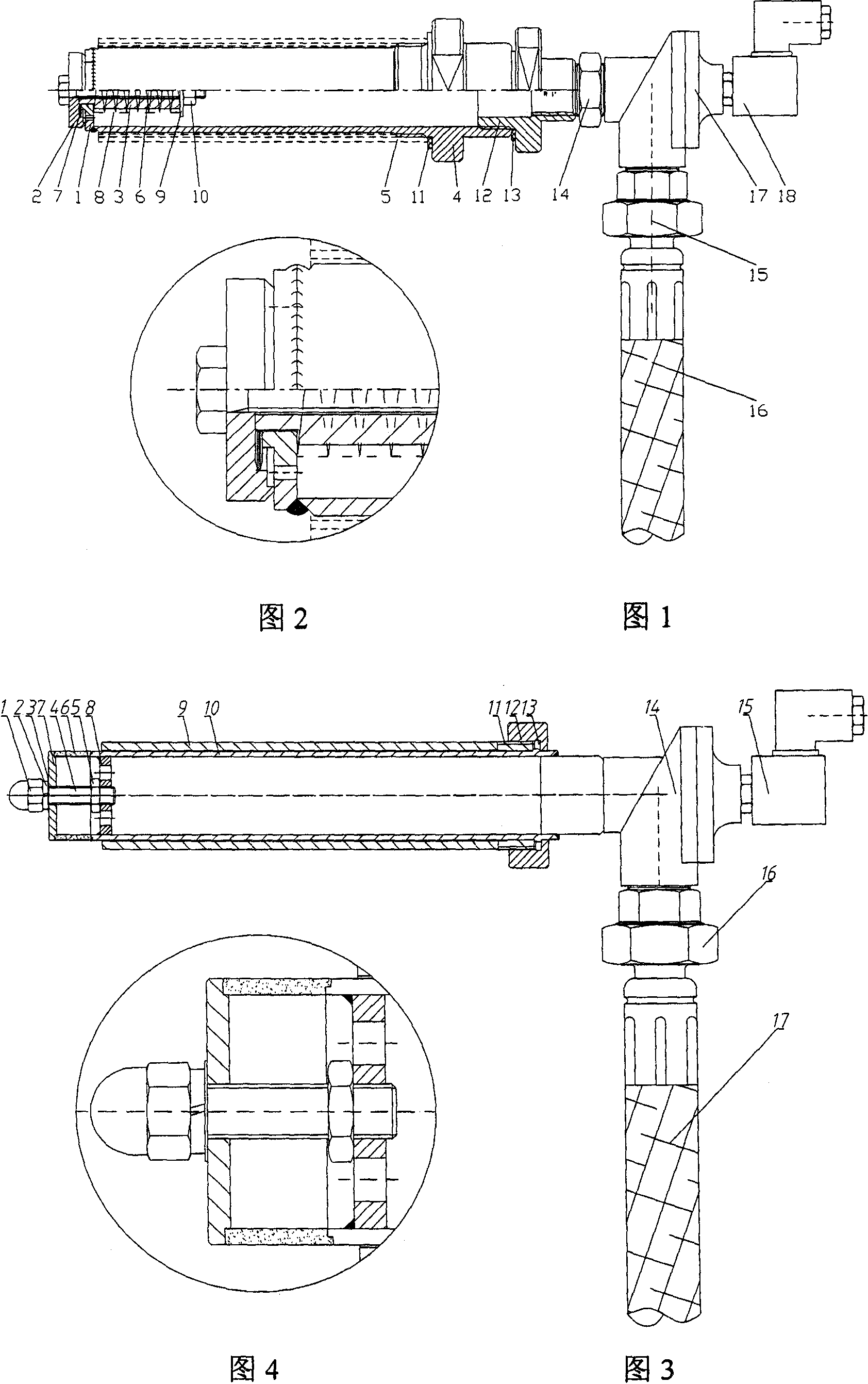
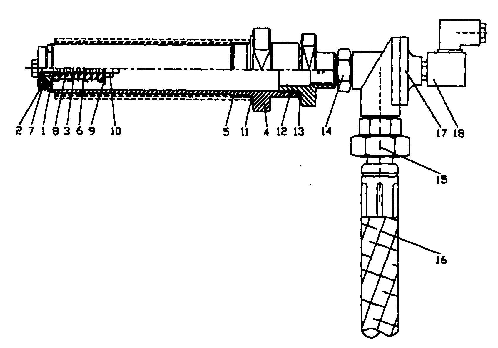
[0030] attached figure 1 The name of the gasification nozzle components shown: nozzle 1, pressure plate 2, spring seat 3, nozzle body 4, gasification nozzle outer connection cylinder 5, hexagonal bolt 6, butterfly spring 7, spring 8, flat washer 9, nut 10, Polytetrafluoro pad 11, variable-diameter connector 12, polytetrafluoro pad 13, short wire 14, rubber hose union joint 15, air intake rubber tube 16, pulse solenoid valve body 17, pulse solenoid valve coil 18.

[0031] As shown in the figure: the spray head 1 is welded on the front end of the nozzle body 4 . Pressing plate 2, nozzle 1, butterfly spring 7, spring 8, and spring seat 3 are connected together by hexagonal bolt 6 M10×85 flat washer 9∮11 and nut 10M10. A polytetrafluoro gasket 11∮75×∮61×3 is installed between the outer connecting cylinder 5 of the gasification nozzle and the nozzle body 4 for sealing, and is connected by an internal thread. A polytetrafluoro gasket 13∮70×∮51×5 is installed between the variable-d...

Embodiment 2

[0035] attached image 3 Gasification nozzle component name: cap nut 1, spring washer 2, flat gasket 3, hexagonal bolt 4, locking thin nut 5, nozzle 6, pressure plate 7, nozzle connection plate 8, nozzle outer connection cylinder 9, nozzle body 10 , Retaining ring 11, PTFE gasket 12, lock nut 13, pulse solenoid valve body 14, pulse solenoid valve coil 15, rubber hose union joint 16, intake rubber tube 17.

[0036]As shown in the figure: the nozzle connecting plate 8 is welded on the front end of the nozzle body 10 . The annular nozzle 6 is fixed on the nozzle connecting plate 8 through the cap nut 1 spring washer 2 flat gasket 3 pressure plate 7 hexagonal bolt 4M10×20 thin locking nut 5 . The nozzle outer connecting cylinder 9 is fixed on the ash hopper or the ash storehouse by welding. A polytetrafluoro gasket 12∮75×∮61×3 is installed between the nozzle body 10 and the nozzle outer connecting cylinder 9 for sealing, and is connected together by a retaining ring 11 and a loc...

Embodiment 3

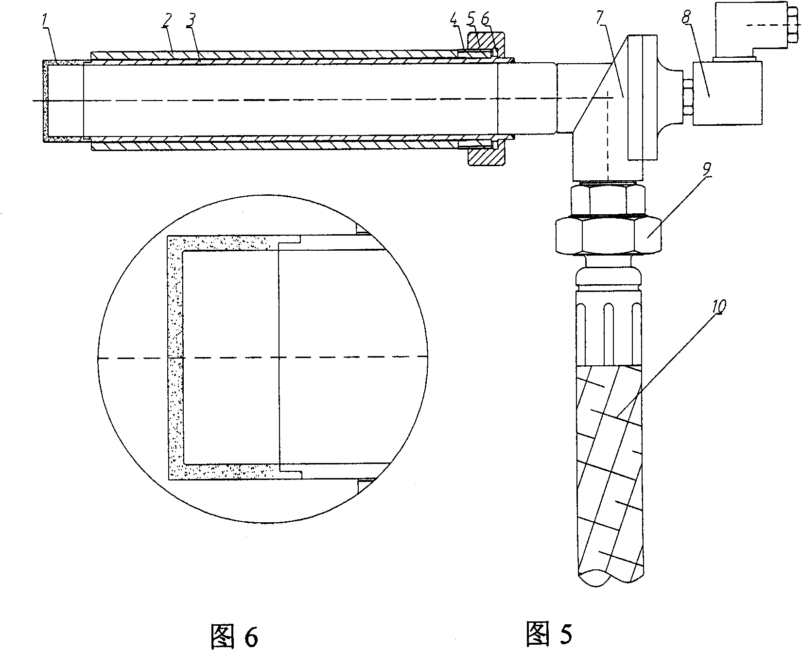
[0040] attached Figure 5 Gasification nozzle component name: annular nozzle 1, nozzle outer connection cylinder 2, nozzle body 3, retaining ring 4, PTFE gasket 5, lock nut 6, pulse solenoid valve body 7, pulse solenoid valve coil 8, rubber hose Union joint 9, air intake rubber pipe 10.

[0041] As shown in the figure: the annular nozzle 1 is welded on the front end of the nozzle body 3 . The nozzle outer connecting cylinder 2 is fixed on the ash hopper or the ash storehouse by welding. A polytetrafluoro gasket 5∮75×∮61×3 is installed between the nozzle body 3 and the nozzle outer connecting cylinder 2 for sealing, and it is connected together through the retaining ring 4 and the lock nut 6G2 to achieve the purpose of fixing the gasification nozzle. The retaining ring 4 on the nozzle body is welded on the nozzle body 3 . The nozzle body 3 is connected to the gas outlet of the pulse solenoid valve body 7 . The pulse solenoid valve coil 8 is installed on the pulse solenoid v...


PUM


Abstract

The invention relates to a gasification nozzle in a gasification system of containers for storing powdery materials. A spray head (1) is welded at the front end of a nozzle body (4); a pressing plate (2) is connected with the spray head (1); a polytetrafluoroethylene gasket (11) is arranged between a connecting cylinder (5) outside the gasification nozzle and the nozzle body (4) for sealing and the connecting cylinder and the nozzle body are connected through internal threads; a polytetrafluoroethylene gasket (13) is arranged between a reducing connector (14) and the nozzle body (4) for sealing and the reducing connector and the nozzle body are connected through internal threads; the reducing connector (12) is connected with the air outlet end of a pulse electromagnetic valve body (17) through a short thread (14); a pulse electromagnetic valve coil (18) is arranged on the pulse electromagnetic valve body (17); and an air inlet rubber pipe (16) is connected to the air inlet of the pulse electromagnetic valve body (17) through a rubber pipe movable joint (15). The invention can be used in the gasification places of storage devices (transit warehouses, ash buckets and the like) of the powdery materials and the like generated by coal fired power plants (fly ash), cement plants (clinker), iron and steel companies (sintering machines) and the like.

Description

technical field [0001] The invention relates to a gasification nozzle, in particular to storage devices (transfer bins and ash, etc.) bucket) gasification nozzle. Background technique [0002] The widely used gasification system consisting of Roots blower, electric heater and gasification tank is composed of Roots blower, electric heater and gasification tank. The gasification structure is complex and the input cost is high; the failure rate is high and the maintenance cost High; large power consumption, large volume, large floor area; small blowing force, the pressure is only 0.1Mpa can not achieve a good gasification effect; in addition, because the gas used in the gasification tank comes directly from the atmosphere, especially in the south The rainy season or humid air will make the materials in the storage device more likely to harden. Contents of the invention [0003] The object of the present invention is to provide a gasification nozzle, which has a simple struc...

Claims


Application Information

Patent Timeline
IPC IPC(8): B05B9/04B05B12/00B05B1/00
Inventor 岳波
Owner 岳波
Why Eureka
Try Eureka