Milling and turning composite machining tool with turning tool row device and lathe tool changing mechanism

A tool changing mechanism and composite machining technology, which is applied to metal processing machinery parts, positioning devices, metal processing equipment, etc., can solve the problem that the milling and turning composite machining machine cannot realize the intensification and automatic control of the milling process and turning process, affecting the milling and turning process. The degree of automation of compound processing machine tools, the inability to realize automatic tool clamping and tool change of turning tools, etc., achieve the effect of improving processing production efficiency, realizing intensification, and improving angle positioning control.

Inactive Publication Date: 2011-07-06
黑龙江光大数控机床有限责任公司
View PDF0 Cites 1 Cited by
  • Summary
  • Abstract
  • Description
  • Claims
  • Application Information

AI Technical Summary

Problems solved by technology

[0003] The purpose of the present invention is to provide a milling-turning compound processing machine tool with a turning tool row device and a lathe tool changing mechanism, so as to solve the problem that the existing milling-turning compound processing machine tool cannot realize the intensification and automatic control of the connection between the milling process and the turning process , it is impossible to realize the automatic clamping and tool change of the turning tool, which affects the automation degree of the milling and turning machine tool, thereby reducing the production efficiency of the milling and turning machine tool

Method used


Image

  • Milling and turning composite machining tool with turning tool row device and lathe tool changing mechanism
  • Milling and turning composite machining tool with turning tool row device and lathe tool changing mechanism
  • Milling and turning composite machining tool with turning tool row device and lathe tool changing mechanism

Examples


specific Embodiment approach 1

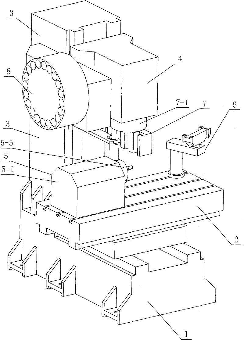
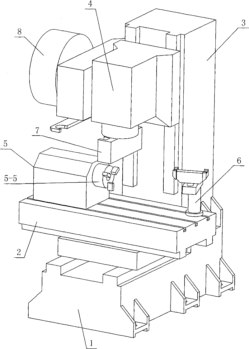
[0020] Specific implementation mode one: as Figure 1-13 As shown, the milling-turning composite processing machine tool with the turning tool row device and the lathe tool changing mechanism described in this embodiment, the composite processing machine tool includes a milling machine main body, and the milling machine main body includes a saddle 1, a workbench 2, a column 3 and the headstock 4, the workbench 2 is horizontally located above the saddle 1 and the two are arranged in a cross shape, the column 3 is located at the rear end of the workbench 2 and the lower end of the column 3 is connected with the slide saddle 1, and the headstock 4 is located on the workbench 2 and the spindle box 4 is slidingly connected with the column 3; the compound processing machine tool also includes a lathe spindle assembly 5, a lathe tool changing mechanism 6 and a turning tool row device 7, and the lathe spindle assembly 5 is arranged on the top of the workbench 2 The left end is sliding...

specific Embodiment approach 2

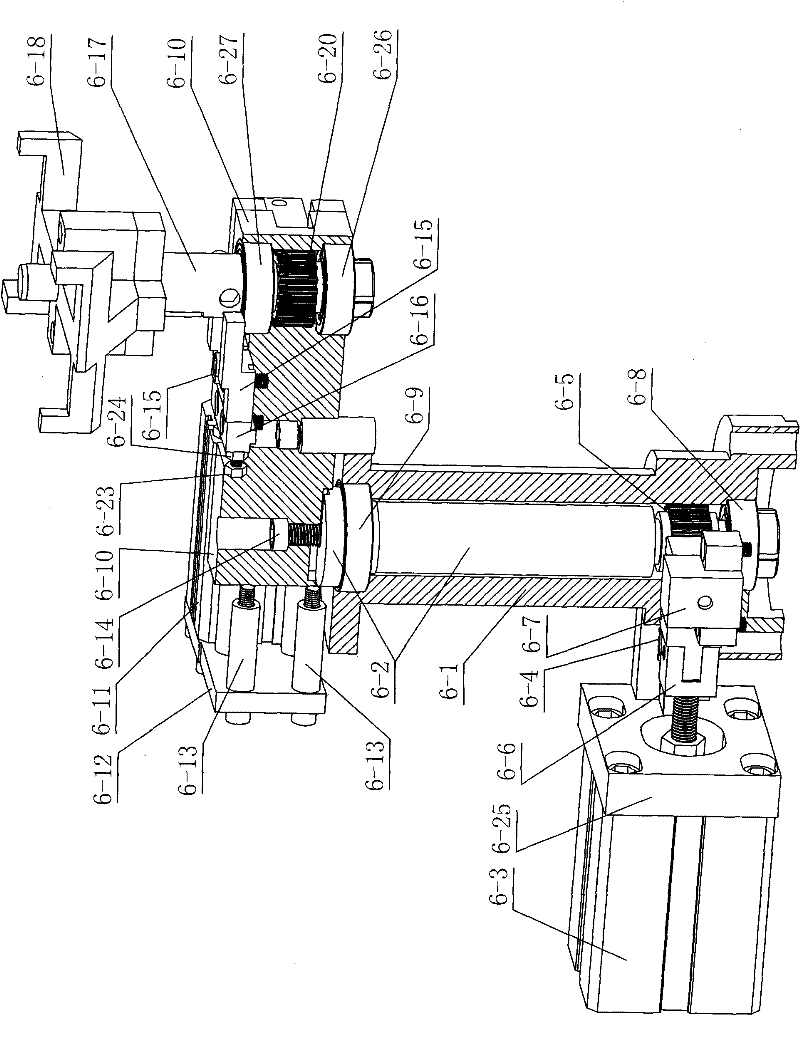
[0025] Specific implementation mode two: as image 3 and Figure 4 As shown, the lathe tool change mechanism 6 in this embodiment also includes a fork-shaped connecting piece 6-6 and a first cylinder connecting plate 6-25, and the piston connecting rod of the first cylinder 6-3 passes through the fork-shaped connecting piece 6-6. It is connected with the first rack 6-4, and the first cylinder 6-3 is connected with the lower end side wall of the shaft sleeve 6-1 through the first cylinder connecting plate 6-25. Such arrangement makes the structure more compact and facilitates assembly. Other components and connections are the same as those in the first embodiment.

specific Embodiment approach 3

[0026] Specific implementation mode three: as image 3 and Figure 4 As shown, the lathe tool changing mechanism 6 in this embodiment also includes a second cylinder connecting plate 6-12, a second cylinder connecting plate connecting piece 6-13 and a second rack connecting plate 6-21, and the second cylinder connecting plate 6-12 is connected with the rocker arm 6-10 through the second cylinder connection plate connector 6-13, and the second cylinder 6-11 is installed on the second cylinder connection plate 6-12. Such arrangement makes the structure more compact and facilitates assembly. Other components and connections are the same as those in the second embodiment.


PUM


Abstract

The invention discloses a milling and turning composite machining tool with a turning tool row device and a lathe tool changing mechanism, and relates to a milling and turning composite machining tool. The milling and turning composite machining tool is to solve the problems that a conventional milling and turning composite machining tool cannot realize the jointed intensiveness and autocontrol of a milling procedure and a turning procedure and cannot realize automatic clamping and tool changing of a turning tool so as to reduce the production efficiency of the milling and turning composite machining tool. A lathe spindle assembly is arranged at the left end of a worktable and in slip connection with the worktable; the lathe tool changing mechanism is fixedly arranged at the right end of the worktable; and the turning tool row device is arranged under a spindle box or on the lathe tool changing mechanism. The milling and turning composite machining tool changes a turning tool changingmode and a turning tool fixing mode of a conventional similar product and improves the production efficiency. Moreover, the milling and turning composite machining tool expands the using functions ofequipment, and a lathe spindle device can be flexibly moved according to practical requirements of users to fully serve as a vertical-type machining and milling center. The milling and turning composite machining tool expands the machining range and the milling effect of the equipment.

Description

technical field [0001] The invention relates to a milling and turning compound processing machine tool, in particular to a milling and turning compound processing machine tool with a turning tool row device and a turning tool changing device, belonging to the field of metal cutting numerical control processing equipment. Background technique [0002] The milling and turning compound processing machine tool integrates the milling function and the turning function, which reduces the footprint of the processing machine tool, reduces the number of clamping and positioning times for processing a workpiece, and saves the time required for process conversion; the milling and turning compound Due to the above advantages, processing machine tools have been widely used in metal cutting. However, the existing milling-turning compound processing machine tools are not equipped with a turning tool row device and a turning tool changing device, so that when the milling process and the turn...

Claims


Application Information

Patent Timeline
Patent Type & Authority Patents(China)
IPC IPC(8): B23P23/02B23Q3/155B23B19/02B23B29/24
Inventor 董海滨马怀念王立平余锦坤
Owner 黑龙江光大数控机床有限责任公司
Why Eureka
Try Eureka