Shuttle-type high-temperature and high-pressure welding check valve

A high-temperature, high-pressure, check valve technology, applied in valve details, control valves, valve devices, etc., can solve problems such as installation at any angle, leakage of special media, limited applicable environment, etc., and achieve simple structure, small opening and closing resistance, The effect of ensuring flatness

Inactive Publication Date: 2010-07-14
WINJET HIGH TECH INVESTMENT BEIJING
View PDF6 Cites 6 Cited by
  • Summary
  • Abstract
  • Description
  • Claims
  • Application Information

AI Technical Summary

Problems solved by technology

[0002] The existing welded check valve is a swing-type welded check valve. Due to the wear and displacement of the lifting lug, the valve disc hits the valve seat, causing vibration and leakage of special media such as high temperature and high pressure, resulting in safety accidents.
The swing welded check valve cannot be installed at any angle, and the applicable environment is limited

Method used


Image

  • Shuttle-type high-temperature and high-pressure welding check valve
  • Shuttle-type high-temperature and high-pressure welding check valve
  • Shuttle-type high-temperature and high-pressure welding check valve

Examples


Embodiment 1

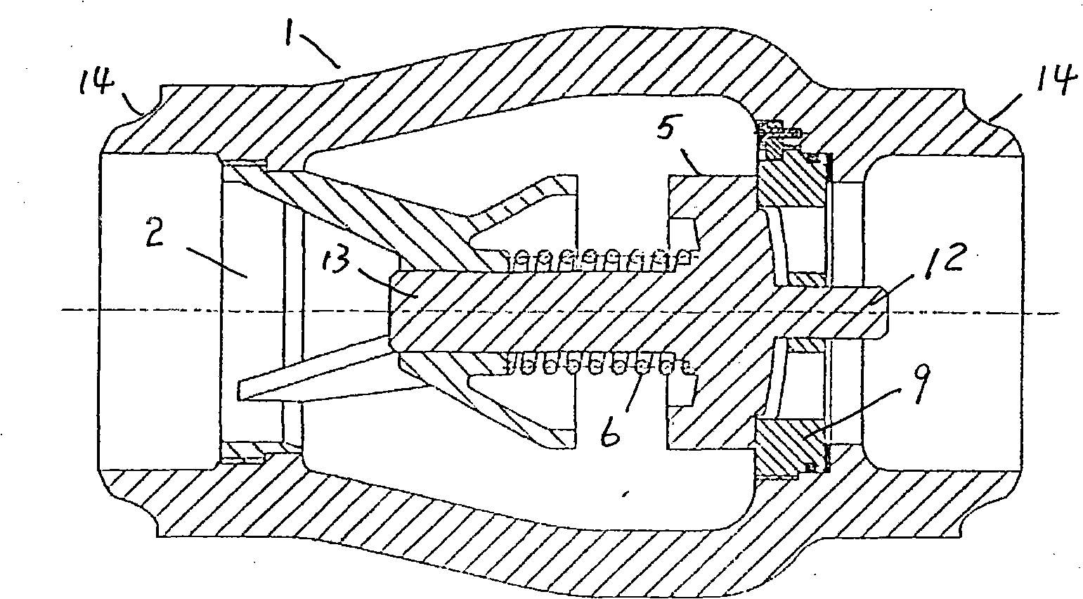
[0021] The middle cavity of the valve body 1 is connected to the joints at both ends in the axial direction, and the outer wall of the port of the joint has welding grooves 14 . The inner wall of the left end joint is threadedly connected with the outer wall of the largest diameter of the valve sleeve 2, and the valve sleeve travels to the right until the end of the left end joint is blocked by a step and stops in place; there is an inner step at the connection between the right end joint and the middle cavity, and the front support 9 is a valve seat , support integrated parts, the front support 9 is installed in the hole on the left side of the inner step, the ring of the front support 9 is the valve seat, the small hole supported by the ribs of the front support 9 is the axial center hole of the front support, and the upstream fluid passes through the ribs Space circulation between strips. The annulus outer diameter of front bearing 9 is less than left end connector step int...

Embodiment 2

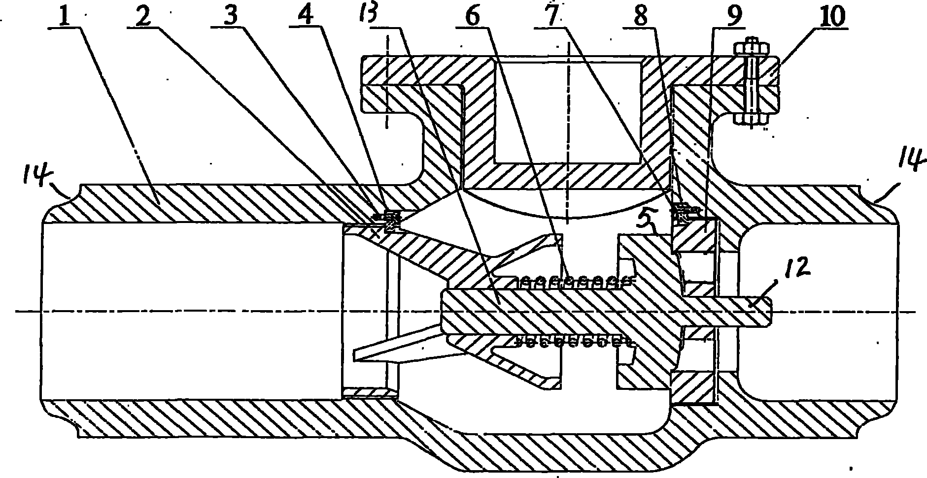
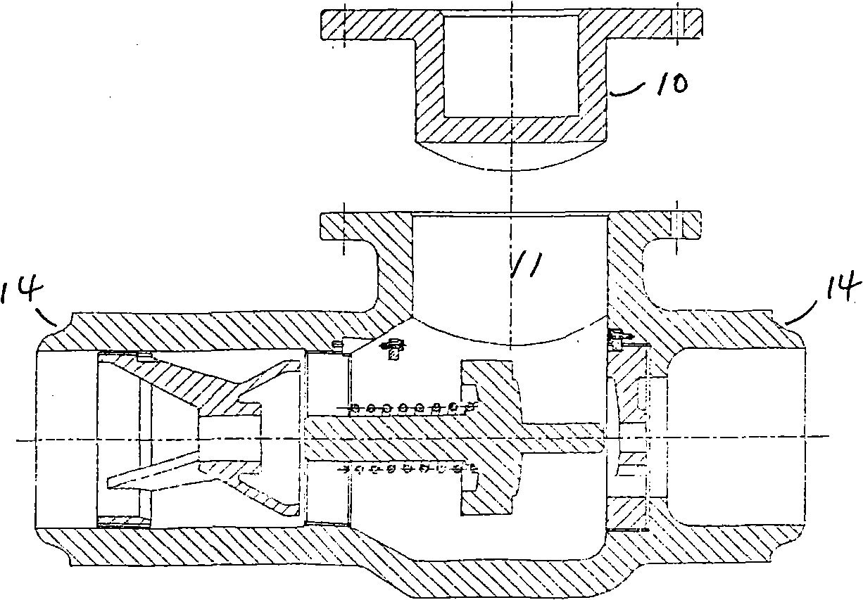
[0023] The middle cavity of the valve body 1 has an inspection hole 11 and the hole cover 10 is connected by flanges and bolts. The axial ends of the middle cavity have left-end threads, right-end steps, left-end threads and the maximum diameter of valve sleeve 2.

[0024] Diameter outer wall threaded connection. The valve sleeve 2 is fixed on the left wall of the middle cavity through a locking pressure piece 4 and a locking screw (or pin) 3 . Front bearing 9 is positioned at the wall hole on the left side of the right end step and is connected with it, and is fixed on the right wall of the middle cavity by locking briquetting block 7 and locking screw (or pin) 8. All the other structures are the same as in Example 1.

[0025] The disassembly process steps of the present invention are as follows:

[0026] a), Disassembly process:

[0027] 1. Take out the inspection hole cover 10: remove the valve sleeve locking screw (or pin) 3 and the valve sleeve locking pressure block ...


PUM


Abstract

The invention relates to a shuttle-type high-temperature and high-pressure welding check valve and solves the problems that the welded check valve cannot be installed at any angle and leakage happens easily. In the shuttle-type high-temperature and high-pressure welding check valve, a middle cavity of a valve body (1) is connected with a coupling at two axial ends, and an outer wall of a port of the coupling is provided with a welding groove (14); the two axial ends of the middle cavity and a connecting passage of the coupling are fixedly connected with a valve bush (2) and a front bearing (9) respectively; a valve flap (5) is in rigid connection with a front shaft (12) and a back shaft (13) which are coaxial; and the front shaft (12) is in movable fit with an axial central hole of the front bearing (9), the back shaft (13) is in movable fit with an axial central hole of the valve bush (2), and the back shaft (13) is sleeved with a spring (6).

Description

Technical field: [0001] The invention relates to a check valve on a high-temperature, high-pressure medium channel, especially a welding check valve. Background technique: [0002] The existing welded check valve is a swing-type welded check valve. Due to the wear and displacement of the lifting lug, the valve disc hits the valve seat to cause vibration and leakage of special media such as high temperature and high pressure, resulting in safety accidents. The swing welded check valve cannot be installed at any angle, and the applicable environment is limited. Invention content: [0003] The purpose of the present invention is to provide a simple structure, no leakage, can be installed at any angle, easy to install and disassemble, both the disc and the valve seat can be taken out, combined in free space, using a safe and reliable shuttle type high temperature and high pressure welding check valve valve. [0004] The present invention is achieved like this: [0005] The ...

Claims


Application Information

Patent Timeline
Patent Type & Authority Applications(China)
IPC IPC(8): F16K15/06F16K27/02
CPCF16K15/063F16K27/0209
Inventor 曾祥炜
Owner WINJET HIGH TECH INVESTMENT BEIJING
Why Eureka
Try Eureka