Electric furnace charging and preheating device

A preheating device and electric furnace technology, applied in the field of metallurgy, can solve the problems of poor scrap preheating effect, increased height of electric furnace equipment, stagnation of popularization and use, etc., and achieves the effect of saving driving power, short overall length, and less equipment maintenance.

Inactive Publication Date: 2010-07-14
CISDI ENG CO LTD
View PDF0 Cites 20 Cited by
  • Summary
  • Abstract
  • Description
  • Claims
  • Application Information

AI Technical Summary

Problems solved by technology

At present, the popular foreign technologies in the world are mainly COSS technology developed based on shaft furnace technology and CONSTEEL technology of vibrating continuous feeding. COSS technology has good technical indicators, but based on the development of electric furnace shaft furnace, the height of electric furnace equipment is increased, and the plant Heightening, the feeding method is intermittent feeding, and there are also environmental protection problems such as dioxins, so its promotion and use tends to stagnate
The CONSTEEL technology based on vibration continuous feeding is a horizontal continuous feeding technology, which can realize stable arc smelting in electric furnaces, is environmentally friendly and reduces electrode consumption, and can greatly reduce the production process costs of electric furnaces. However, in this method, only the upper layer of scrap steel is heated , so the preheating effect of scrap steel is not good, and because the vibration feeding has a large number of moving parts and the high temperature of the flue gas, the equipment maintenance of this system is relatively large, and the mechanical reliability is relatively low

Method used


Image

  • Electric furnace charging and preheating device
  • Electric furnace charging and preheating device
  • Electric furnace charging and preheating device

Examples


Embodiment 1

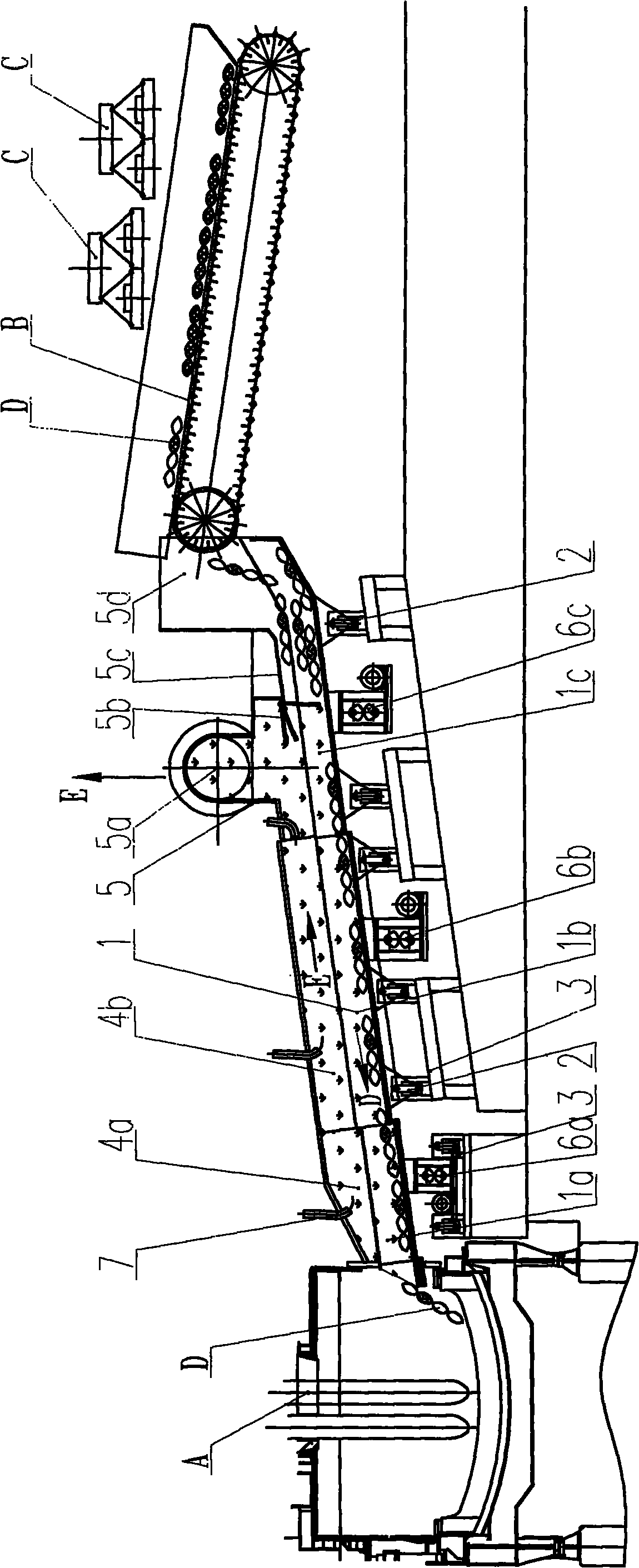
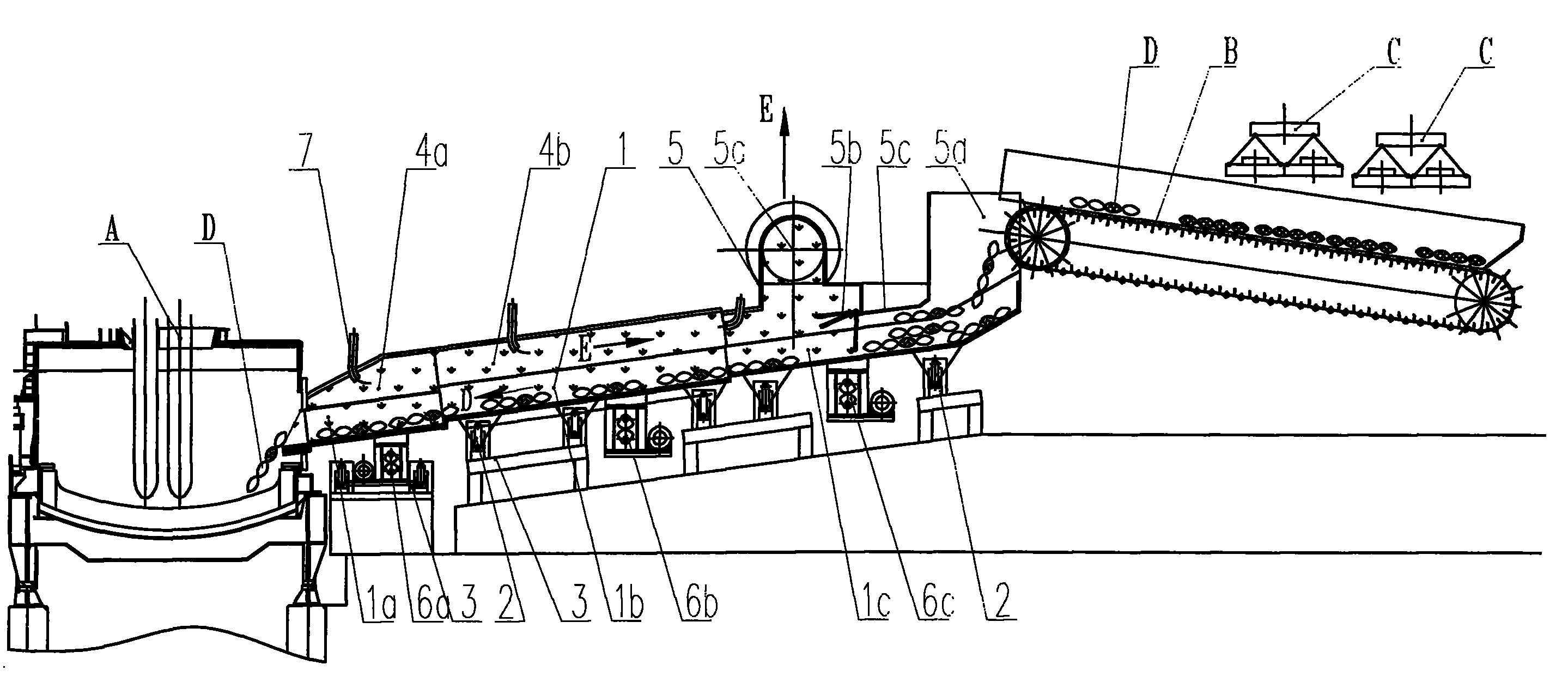
[0027] Embodiment 1: as figure 1 Shown:

[0028] Steel scrap D is loaded onto the plate chain receiving conveyor through the disk crane C (or other equipment). In order to ensure the flow rate of the feeding material, the plate chain receiving conveyor must have sufficient length. The receiving conveyor can be installed obliquely to reduce the hoisting height of the disk crane, and also increase the feeding length of the plate chain receiving conveyor. Of course, the plate chain receiving conveyor can also be set in a curved manner, which can also increase the feeding length. The plate chain receiving conveyor transports the scrap steel D into the high end of the scrap steel conveying chute 1. The bottom 1 of the scrap steel conveying chute is inclined about 10° from the horizontal plane. The plate chain receiving conveyor is set at an inclination angle of 15° from the horizontal plane. And it is arranged in an inverted V shape with the scrap steel conveying chute 1. The in...

Embodiment 2

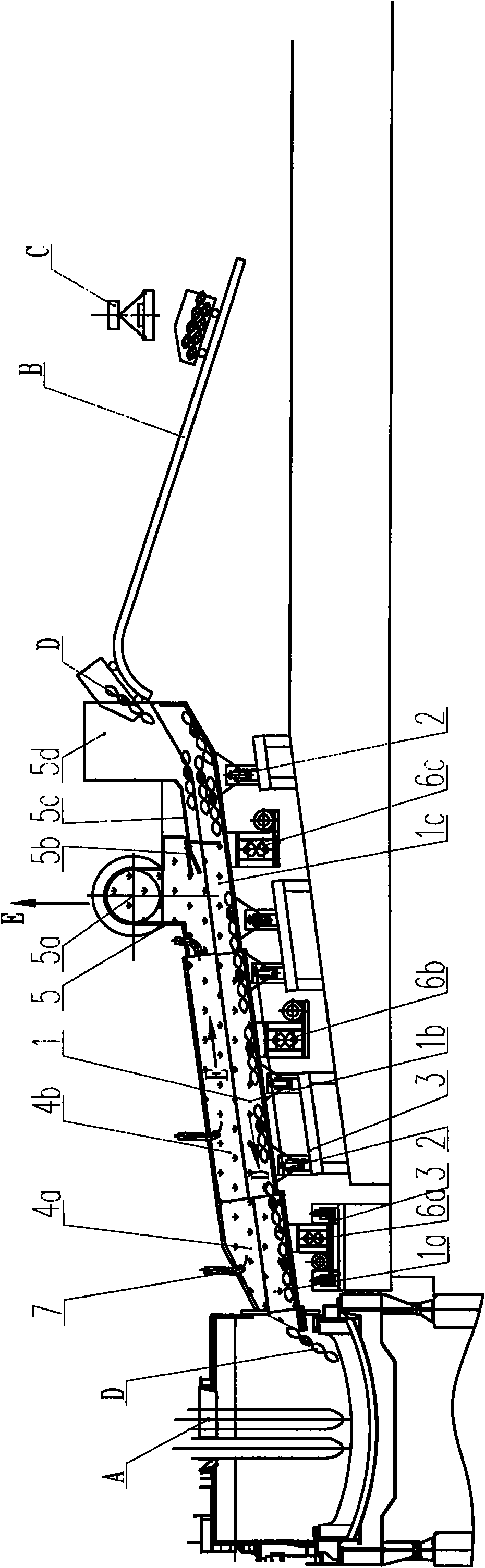
[0034] Embodiment 2: The difference from Embodiment 1 is that piece B is a receiving machine with a ramp trolley, and the inclination angle can be larger. The transportation volume of the ramp trolley in this scheme is small, which is suitable for small electric furnaces.

[0035] The scrap steel conveying chute and the traction type receiving conveyor of the present invention form the conveying process of scrap steel to V shape, which is very similar to the skiing process, so the system is also called SKISTEEL.


PUM


Abstract

The invention belongs to the technical field of metallurgy, and discloses an electric furnace charging and preheating device, comprising a steel scrap conveying chute (1) which is arranged aslant with the horizontal plane; the high end of the steel scrap conveying chute (1) is provided with an inclined pull-type material receiving conveyor (B), and the low end of the steel scrap conveying chute (1) extends into an electric furnace (A) from a pore on the side wall of the electric furnace (A); the upper part of the steel scrap conveying chute (1) is provided with a seal cover which forms a steel scrap and smoke path with the steel scrap conveying chute (1). The electric furnace charging and preheating device of the invention has the advantages of small electric energy consumption, small equipment abrasion, large steel scrap conveying amount and small total length of equipment and is a new energy-saving and environment-protection technology with promotional value in electric furnaces or other production processes.

Description

technical field [0001] The invention belongs to the technical field of metallurgy and discloses an electric furnace feeding and preheating device, in particular to a combined continuous feeding and preheating device of an electric furnace scrap steel chute and a traction type receiving conveyor. Background technique [0002] Electric furnace steelmaking is an important steelmaking method that melts scrap metal by an electric arc, which consumes a lot of electrical energy during the smelting process. The continuous feeding and preheating technology of electric furnace scrap steel is an important sub-item technology of electric furnace steelmaking. It can save a lot of electric energy, reduce the temperature of flue gas and the emission of dust in it, and can stabilize the electric arc smelting of electric furnace and reduce the noise of electric furnace. It is a new technology of energy saving and environmental protection. At present, the popular foreign technologies in the ...

Claims


Application Information

Patent Timeline
Patent Type & Authority Applications(China)
IPC IPC(8): F27D3/00F27D13/00
Inventor 黄其明徐杰刘向东高瞻
Owner CISDI ENG CO LTD
Why Eureka
Try Eureka