2*2 long period fiber bragg grating coupler

A fiber grating and coupler technology, applied in the coupling of optical waveguide, cladding fiber, optical waveguide light guide, etc., can solve the problem of non-reconfigurable and achieve the effect of easy writing and erasing

Inactive Publication Date: 2010-07-14
UNIV OF ELECTRONICS SCI & TECH OF CHINA
View PDF0 Cites 12 Cited by
  • Summary
  • Abstract
  • Description
  • Claims
  • Application Information

AI Technical Summary

Problems solved by technology

Therefore, a coupler constructed with such two fiber gratings written with a powerful laser is not reconfigurable

Method used


Image

  • 2*2 long period fiber bragg grating coupler
  • 2*2 long period fiber bragg grating coupler
  • 2*2 long period fiber bragg grating coupler

Examples


Embodiment 1

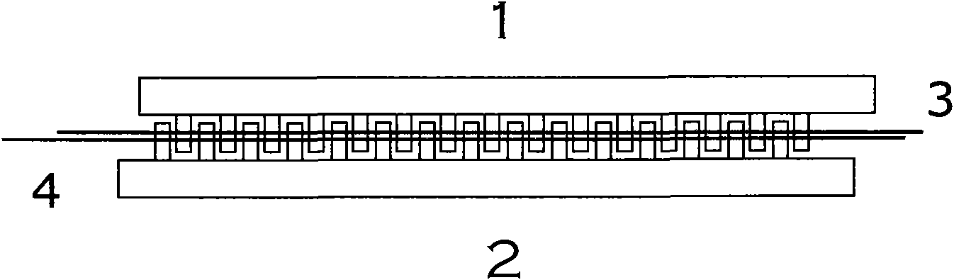
[0037] figure 1 It is a structural diagram of a specific embodiment of the 2×2 long-period fiber grating coupler of the present invention.

[0038] In this embodiment, the reconfigurable 2×2 long-period fiber grating coupler of the present invention can be implemented according to the following steps:

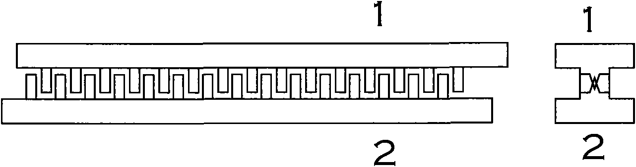
[0039] Step 1: Manufacture two toothed force applying units 1 and 2 with V-shaped grooves with the same specific period by machining, such as Figure 4 shown.

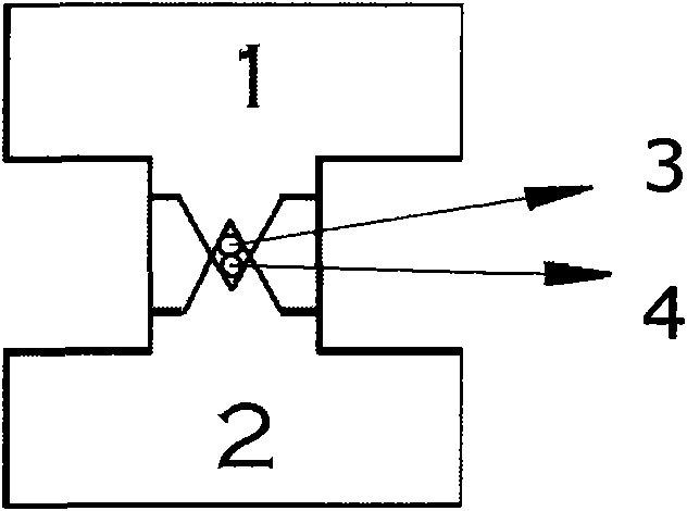
[0040] Step 2: Put two bare fibers 3 and 4 into Figure 4 In the V-shaped groove of the force application unit 2 shown, another force application unit 1 is placed above, that is, the V-shaped periodic grooves of the two force application units 1 and 2 are inserted into each other and simultaneously press the two bare optical fibers 3 and 4 ,Such as figure 1 and figure 2 shown. This structure ensures that the two bare optical fibers 3 and 4 clamped in the two V-shaped periodic grooves can be in close contact, and ...

Embodiment 2

[0043] Figure 5 It is a transmission coupling characteristic diagram under a specific implementation mode of the 2×2 long-period fiber grating coupler of the present invention.

[0044] In the present embodiment, the long-period grating period Λ=0.6mm produced by the periodic radial pressure, according to the test, the fundamental mode of the core and the third-order cladding mode in the common single-mode fiber near the wavelength of 1550nm satisfy (1) formula conditions. We used two toothed force applying units with V-shaped grooves, and clamped two bare optical fibers according to the steps in Embodiment 1. The parameters of the V-shaped periodic groove are: period 0.6mm, tooth width 0.2mm, and 100 pressing teeth. When the photoelastic effect and microbending effect under the pressure of 2.5Kg heavy objects cause the fiber to produce long-period fiber gratings, the grating couples the fundamental mode of the fiber core with the third-order cladding mode, and the evanesce...


PUM


Abstract

The invention discloses a 2*2 long period fiber Bragg grating coupler which comprises a force applying device, and two pieces of closely contacted and parallel arranged bare optical fibers without protective layers, namely, transmission fiber and coupling fiber. The force applying device periodically applies radial pressure with period Lambada being hundred-micron magnitude on the axial propagation of the optical fibers, thus gratings with equivalent spatial variation are written on the axial propagation of the bare optical fibers. When spatial period of fiber Bragg grating causes fiber core fundamental modes and higher order cladding modes to satisfy the phase position matching condition, the fiber core fundamental modes and the cladding modes of the transmission fiber and the coupling fiber perform intercoupling; besides, cladding modes of the transmission fiber and the coupling fiber perform intercoupling under action of evanescent field. Based on the couplings, periodical radial pressure plays the role of a coupler on the two pieces of bare optical fibers. As the long period fiber Bragg grating is only generated by external force, the long period fiber Bragg grating coupler is a wavelength choice direction coupler easy to write and erase, and can be applied to optical communication network as a flexible add / drop multiplexer and the like.

Description

technical field [0001] The invention relates to the technical field of information optics and optoelectronic devices, in particular to a 2×2 long-period fiber grating coupler in optical communication technology. Background technique [0002] 2×2 optical fiber coupler is the most commonly used optical passive device in optical fiber communication and optical fiber sensing technology, and can be used as beam splitter, wavelength division multiplexer, etc. [0003] In a single-mode fiber, the distribution of the fundamental mode light field is mainly concentrated in the core region, and the light field in the cladding decays exponentially with the radial distance of the fiber. The coupling coefficient between the fundamental modes of two parallel-arranged optical fibers is proportional to the overlap integral of the fundamental-mode light field, so the coupling between the fundamental modes of two parallel-arranged optical fibers is extremely weak. In order to obtain an arbitr...

Claims


Application Information

Patent Timeline
Patent Type & Authority Applications(China)
IPC IPC(8): G02B6/28G02B6/02
Inventor 周晓军黎晓云陈成金张旨遥兰岚
Owner UNIV OF ELECTRONICS SCI & TECH OF CHINA
Why Eureka
Try Eureka