Valve gear control device for internal combustion engine
A technology for control devices and internal combustion engines, applied in valve devices, mechanical equipment, transportation and packaging, etc., can solve the problems of cumbersome processing and complicated oil circuit formation, and achieve the effects of improving sealing, realizing miniaturization, and improving installation rigidity.
- Summary
- Abstract
- Description
- Claims
- Application Information
AI Technical Summary
Problems solved by technology
Method used
Image
Examples
no. 1 example
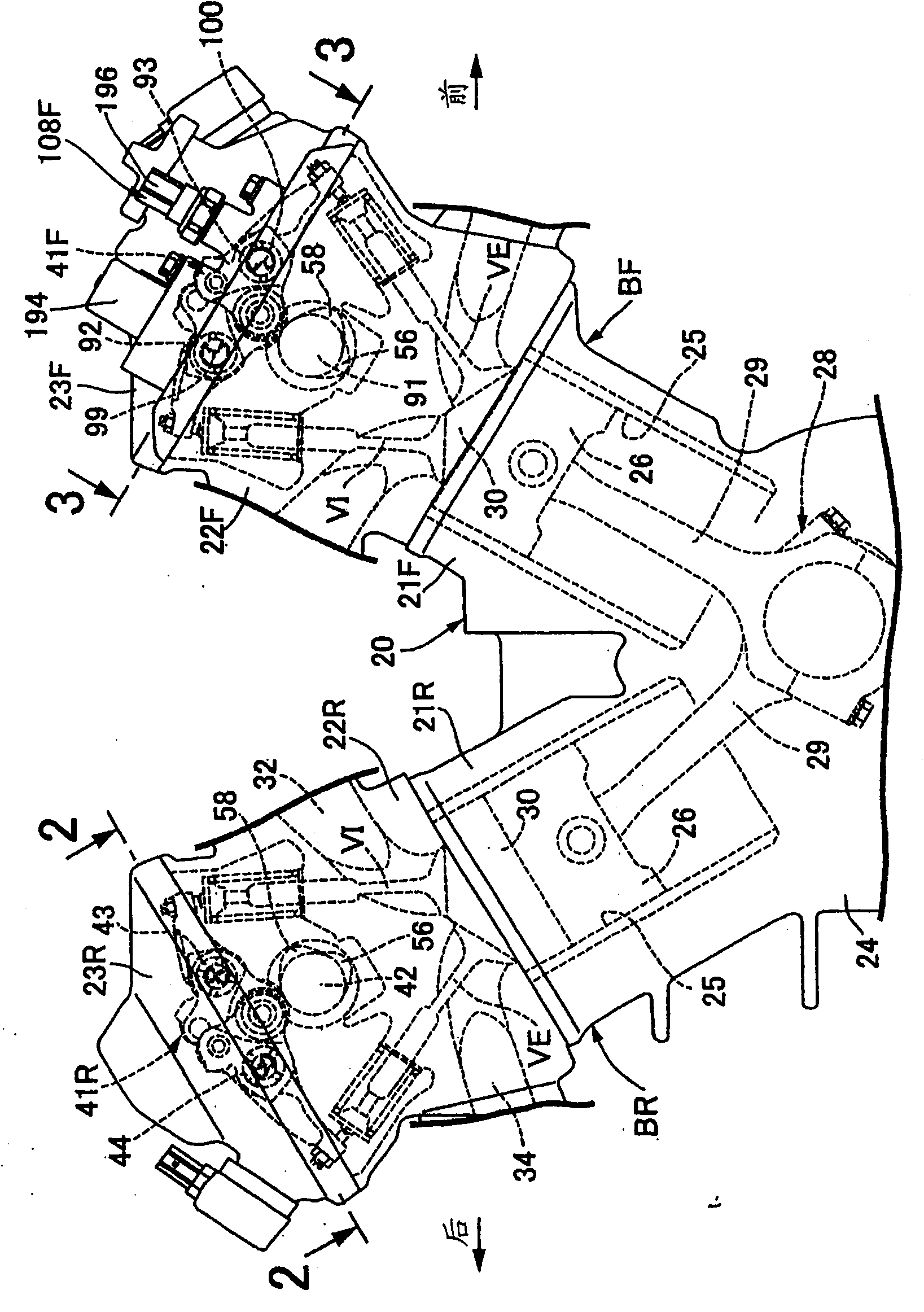
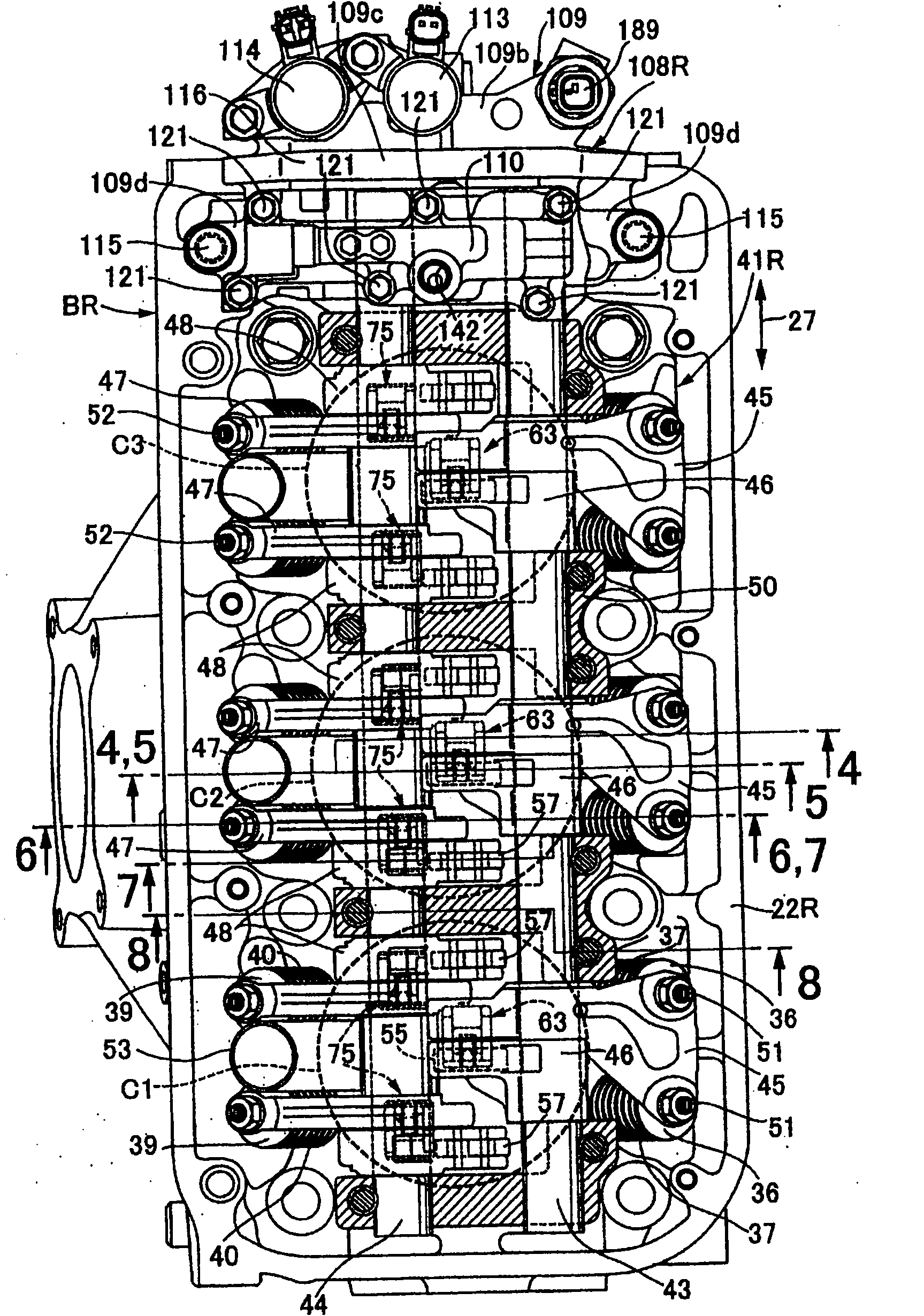
[0047] First, in figure 1 Among them, the internal combustion engine main body 20 of the V-type multi-cylinder internal combustion engine mounted on a vehicle has a rear cylinder bank BR, and is arranged in a V-shaped manner in front of the rear cylinder bank BR in cooperation with the rear cylinder bank BR. Cylinder bank BF. The rear bank BR is composed of a rear cylinder block 21R, a rear cylinder head 22R coupled to the upper end of the rear cylinder block 21R, and a rear cylinder head cover 23R coupled to the rear cylinder head 22R. The front bank BF is composed of a front cylinder block 21F, a front cylinder head 22F joined to the upper end of the front cylinder block 21F, and a front head cover 23F joined to the front cylinder head 22F. Also, the rear and front cylinder blocks 21R, 21F are integrally formed with the crankcase 24 .
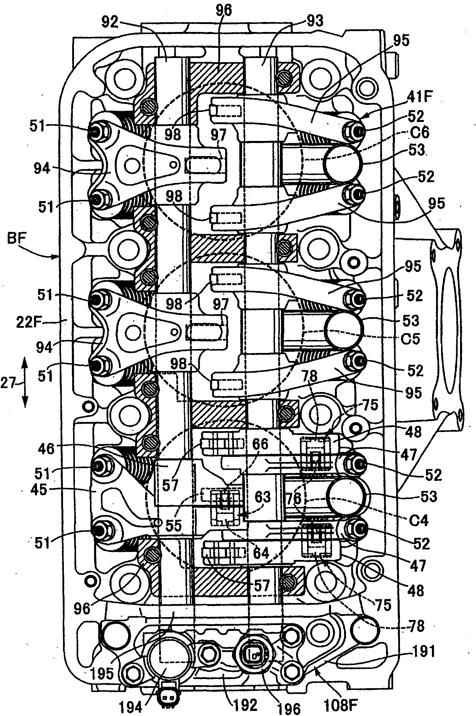
[0048] Rear cylinder bank BR as figure 2 As shown, there are first, second and third cylinders C1 , C2 , C3 arranged in series from the ...
PUM
 Abstract
Description
Claims
Application Information
 - R&D
- Intellectual Property
- Life Sciences
- Materials
- Tech Scout
- Unparalleled Data Quality
- Higher Quality Content
- 60% Fewer Hallucinations
Browse by: Latest US Patents, China's latest patents, Technical Efficacy Thesaurus, Application Domain, Technology Topic, Popular Technical Reports.
© 2025 PatSnap. All rights reserved.Legal|Privacy policy|Modern Slavery Act Transparency Statement|Sitemap|About US| Contact US: help@patsnap.com


