Drying tower with multi-helical structure and drying method

A technology of spiral structure and drying tower, which is applied in application, food preparation, food science, etc., to achieve the effect of avoiding uneven drying

Inactive Publication Date: 2010-07-21
SHANGHAI YI CHEN INFORMATION TECH DEV
View PDF8 Cites 6 Cited by
  • Summary
  • Abstract
  • Description
  • Claims
  • Application Information

AI Technical Summary

Problems solved by technology

Although the powder and granular materials are divided into several groups, which can promote the uniform drying of the materials,

Method used


Image

  • Drying tower with multi-helical structure and drying method
  • Drying tower with multi-helical structure and drying method
  • Drying tower with multi-helical structure and drying method

Examples


Example Embodiment

[0065] Embodiment one:

[0066] A drying tower comprising the following parts:

[0067] according to figure 1 :

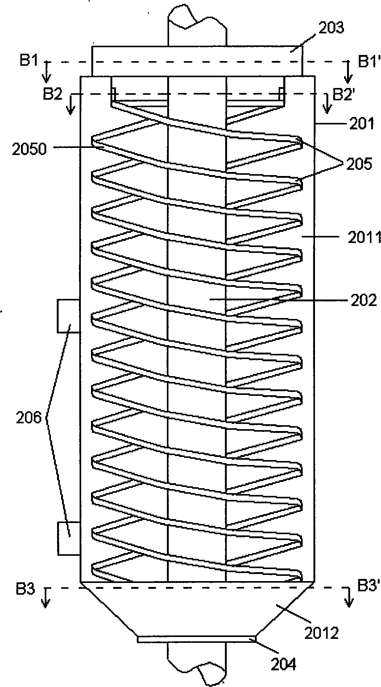
[0068] A drying tower includes a shell 201 , a rotating shaft 202 , a material inlet 203 , a material outlet 204 , a spiral material channel 205 , and a rotating wind generator 206 .

[0069] The casing 201 includes a cylindrical tower drying chamber 2011 at the upper part and a conical storage chamber 2012 at the lower part.

[0070] according to Figure 2a and 2b :

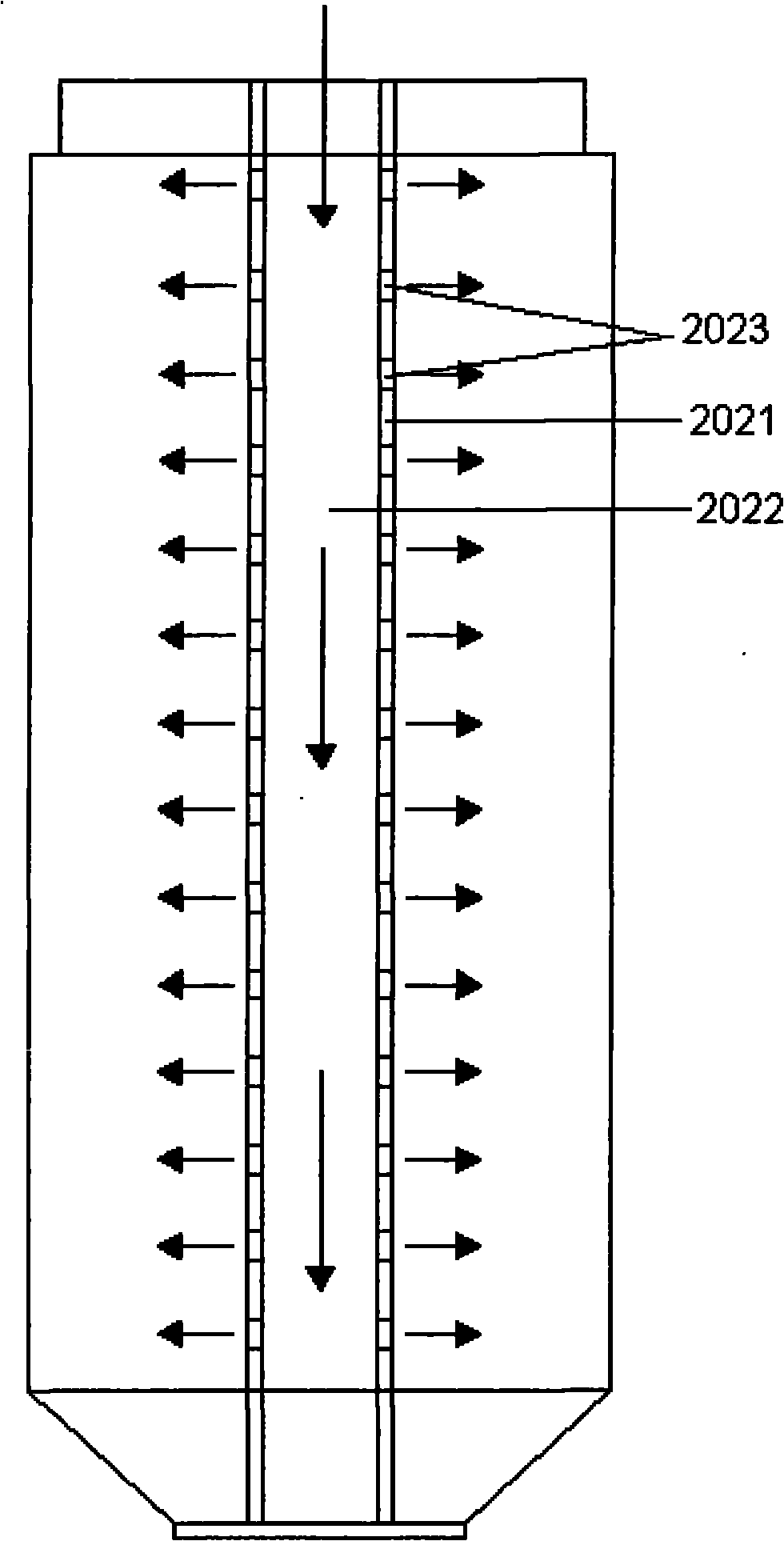
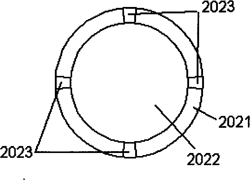
[0071] The rotating shaft 202 is located at the center of the casing 201 , passing through the axes of the tower drying chamber 2011 and the conical storage chamber 2012 in sequence. The rotating shaft 202 includes a shaft housing 2021 , a shaft cavity 2022 surrounded by the shaft housing 2021 and a set of one-way holes 2023 disposed on the shaft housing 2021 .

[0072] The one-way hole 2023 passes through the shaft housing 2021 and communicates with the shaft cavity 2022 to allow the gas insi...

Example Embodiment

[0113] Embodiment two:

[0114] Adopt the following technical parameters to improve embodiment one:

[0115] The spiral material channel 205 is a set of spiral slides 2050 rotating around the shaft 202 , including two spiral slides 2050 .

[0116] In the spiral slideway 2050, the angle b1 between the retaining structure 2053 and the spiral structure 2052 is 81°.

[0117] The slope b5 between the spiral structure 2052 and the horizontal plane is 11°.

[0118] In the feed port 203, the central angle b2 of the material feed port 2035 is 90°.

[0119] In the discharge port 204, the central angle b3 of the storage chamber 2042 is 90°.

[0120] The drying device includes one rotating wind generator 206, and the angle b4 formed between the air outlet 2063 and the horizontal plane is 68°.

Example Embodiment

[0121] Embodiment three:

[0122] Adopt the following technical parameters to improve embodiment one:

[0123] The spiral material channel 205 is a set of spiral slides 2050 rotating around the shaft 202 , including two spiral slides 2050 .

[0124] In the spiral slideway 2050, the angle b1 between the retaining structure 2053 and the spiral structure 2052 is 91°.

[0125] The slope b5 between the spiral structure 2052 and the horizontal plane is 21°.

[0126] In the feed port 203, the central angle b2 of the material feed port 2035 is 50°.

[0127] In the discharge port 204, the central angle b3 of the storage chamber 2042 is 50°.

[0128] The drying device includes two rotating wind generating devices 206, and the angle b4 between the air outlet 2063 and the horizontal plane is 65°.


PUM

PropertyMeasurementUnit
Center angleaaaaaaaaaa
Central angleaaaaaaaaaa

Abstract

The invention discloses a drying tower with a multi-helical structure and a drying method thereof. The drying tower comprises a shell, a rotating shaft, a feed port, a discharge port, a helical material passage and a whirling wind generating device, wherein the rotating shaft is positioned in the centre of the shell and comprises a shaft shell, a shaft cavity enclosed by the shaft shell and a group of unidirectional holes arranged on the shaft shell; the helical material passage consists of a group of helical sliding ways which whirls around the rotating shaft and comprises 2 to 6 helical sliding ways; and the helical sliding way has a uniform-width band-like structure which whirls around the rotating shaft and comprises an inlet end, a helical structure and a material stopping structure.

Description

technical field [0001] The invention relates to a drying tower, in particular to a drying tower with multiple helical structures. [0002] The invention also relates to a drying method using a drying tower with a multi-helical structure. Background technique [0003] During the processing of reconstituted rice, it is necessary to dry and cool the reconstituted rice particles after extrusion and cutting. However, the reconstituted rice granules after extrusion and cutting have higher water content and higher temperature, and the starch component therein will undergo gelatinization under the conditions of high temperature and high humidity, so that the outer surface of the reconstituted rice granules has a higher viscosity. This also resulted in a greater degree of sticking between the reconstituted rice grains. [0004] For the drying of solid granular materials, tower dryers, drum dryers, etc. are often used to take away the moisture of solid granular materials under the c...

Claims


Application Information

Patent Timeline
IPC IPC(8): A23L1/10A23L7/10
Inventor 刘英
Owner SHANGHAI YI CHEN INFORMATION TECH DEV
Why Eureka
Try Eureka