A Single Locomotive Fixed Rolling Test Bench

A rolling test bench and locomotive technology, applied in railway vehicle testing and other directions, can solve the problems of unstable locomotive operation, high requirements for test workshops, dynamic instability, etc., achieve simple, effective and reliable synchronization, shorten test preparation time, and work speed range. wide effect

Inactive Publication Date: 2011-12-21
SOUTHWEST JIAOTONG UNIV
View PDF0 Cites 0 Cited by
  • Summary
  • Abstract
  • Description
  • Claims
  • Application Information

AI Technical Summary

Problems solved by technology

The locomotive is tested on the test bench, and its speed is only reflected by the locomotive wheel speed, and the car body does not move. Therefore, the equivalent moment of inertia reflected in the traction motor rotation dynamics equation is reduced to about 1 / 20 of the line operation. Influenced by the locomotive closed-loop control system designed according to the running conditions of the line, the speed may be unstable in the fixed rolling test
The dynamic instability of this kind of locomotive is the main obstacle to the realization of electrical synchronous adjustment accuracy. Many test bench scheme designs do not understand this, and there are no corresponding structural measures
[0016] 3) The stationary rolling test bench simulates the test process of two infinitely long straight rails through multiple independent track wheelsets. Many factors will cause the speed of each track wheel set to be different, making the locomotive mistaken for a certain track wheel set. Some wheel sets stop torque output due to idling, and then resume output to them, making the locomotive run unstable; especially when the locomotive starts, the output torque will stop frequently, making the locomotive unable to start normally
The existence of the shift gear box not only makes the equipment of the test bench complicated, the cost is high, but also makes the installation and adjustment complicated
[0019] 5) The complex synchronous mechanical connection parts, the gear shifting gearbox and the motor driving the track wheel can only be installed on the side of the track wheel set, so that the installation area requires a width of more than 6 meters
Therefore, the requirements for the test plant are high, the test operation is complicated, and due to the limitation of the site, it is difficult to build a fixed rolling test bench in the existing maintenance plant and section
[0020] In short, the existing test bench uses a DC motor to provide dynamic / resistance torque, and the electrical synchronization mainly relies on the DC motor to adjust the armature or excitation.

Method used


Image

  • A Single Locomotive Fixed Rolling Test Bench
  • A Single Locomotive Fixed Rolling Test Bench
  • A Single Locomotive Fixed Rolling Test Bench

Examples


Embodiment 1

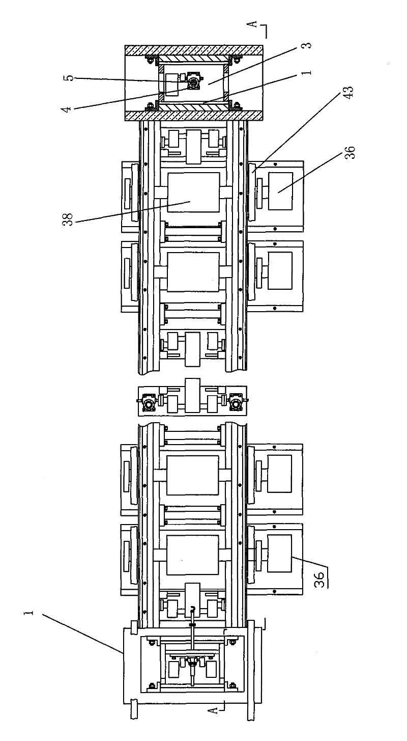
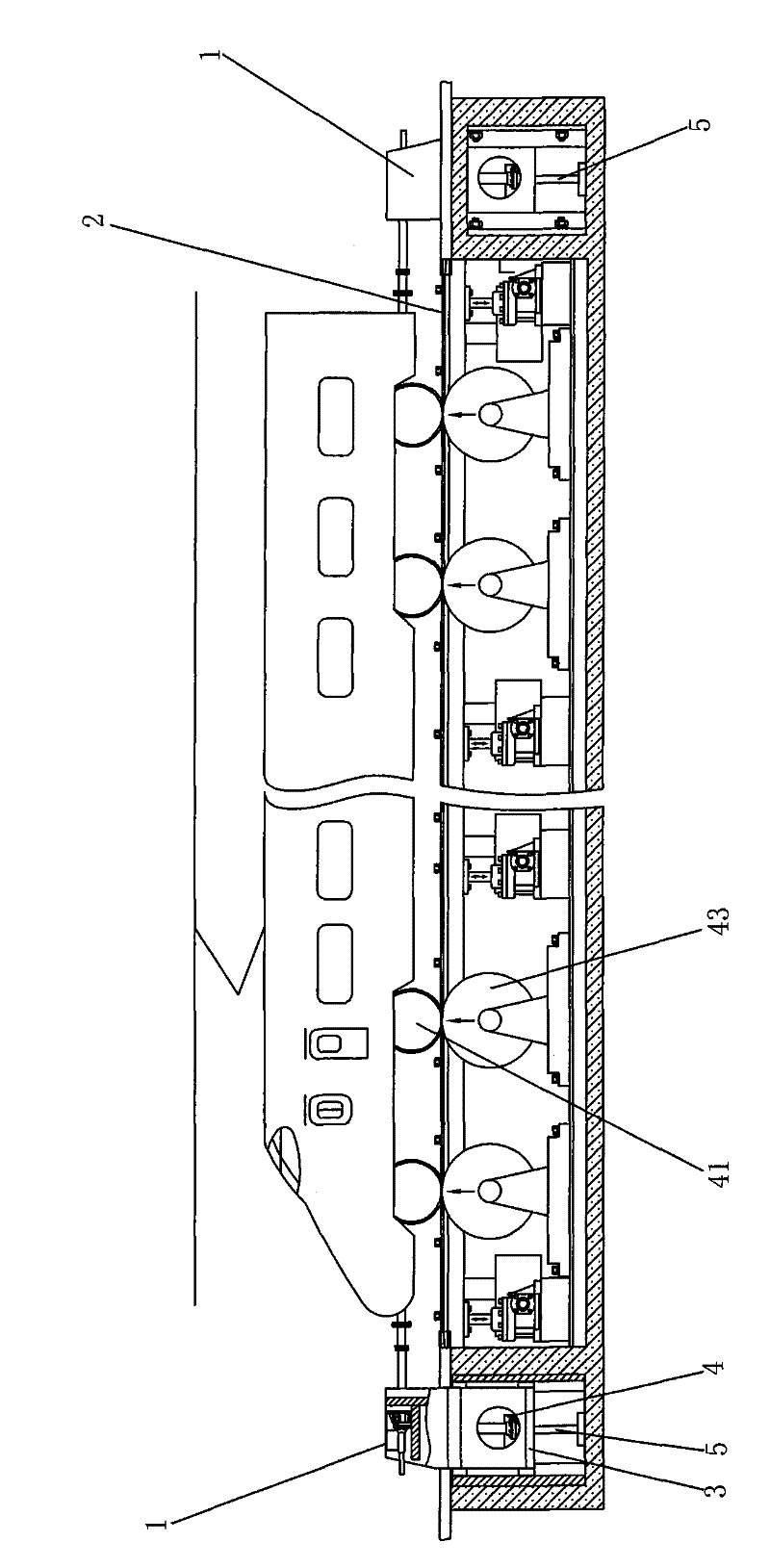
[0064] figure 1 , image 3 , Figure 7 As shown, a specific embodiment of the present invention is: a fixed rolling test bench for a single locomotive, including two reaction force frames 1 and an upper axle 2, and the same number of test units as the wheel pairs 41 of a single locomotive. The test unit group, wherein: the composition of the test unit is that the shaft of the rail wheel pair 43 supporting the locomotive wheel pair 41 is connected to the winding asynchronous motor 36 shafts; the diameter / length ratio of the winding asynchronous motor is greater than 1, and the rail wheel To the middle part of the axle of (43), flywheel (38) is also installed, and flywheel 38 shares bearing with track wheel pair 43.

[0065] Figure 7 It shows that the stator windings of the wound asynchronous motors 36 of each test unit in the test unit group are connected in parallel through the stator three-phase busbar 53, and the stator busbar 53 is connected with the power grid through ...

Embodiment 2

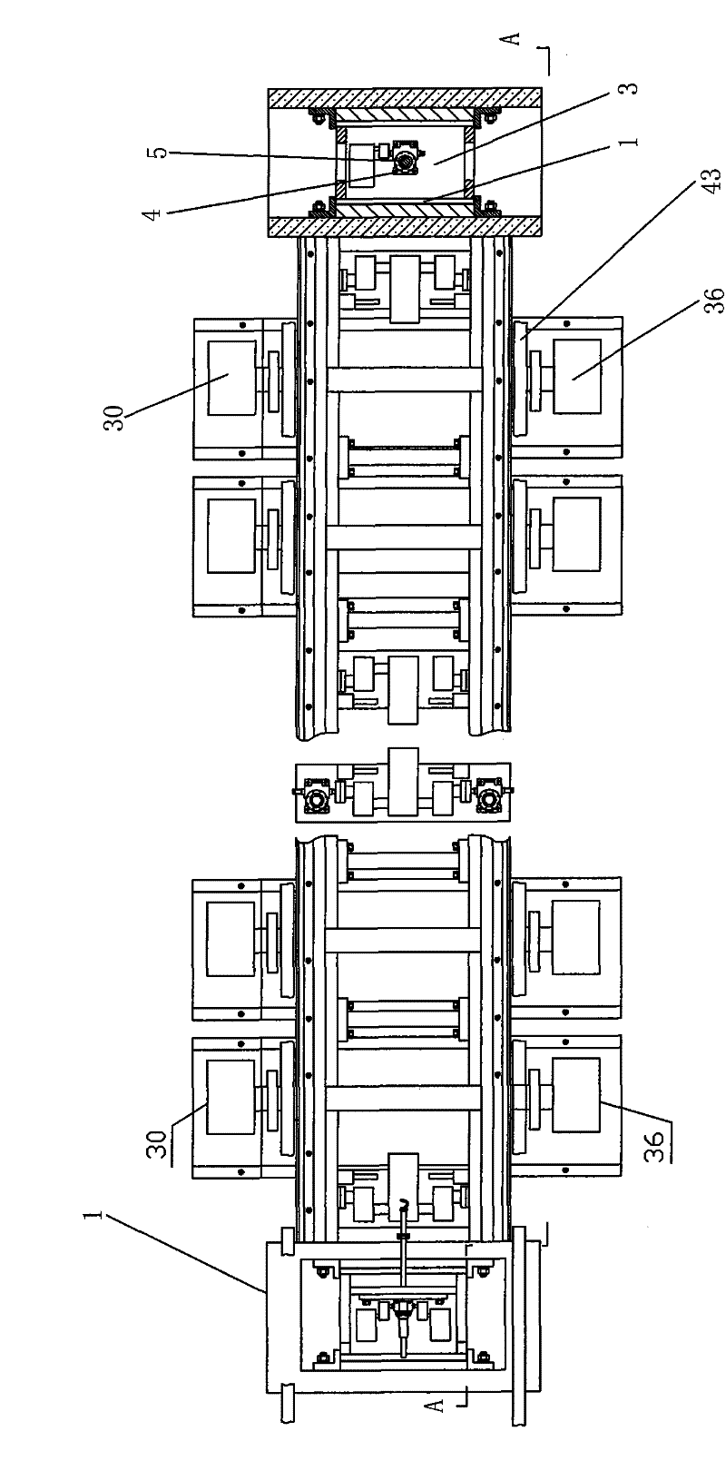
[0070] figure 2 , image 3 , Figure 5 , Image 6 , Figure 8 As shown, the structure of this example is basically the same as that of Embodiment 1, and the difference is that the shaft of the track wheel pair 43 is also connected with the shaft of the synchronous motor 30 at the same time, and the diameter / length ratio of the synchronous motor 30 is greater than 1; the track wheel pair 43 There is no flywheel installed.

[0071] In the test unit group, the electrical connection mode of the synchronous motor 30 of each test unit is: the stator winding of the synchronous motor 30 is connected to the synchronous motor stator three-phase busbar 61 in parallel; the synchronous motor stator three-phase busbar 61 is connected to the The three star-connected capacitors 2 77 are also connected to the three star-connected energy consumption resistors 2 75 through the switch 8 64 , and the rotor windings of the synchronous motor 30 are connected in series with each other, and then ...


PUM


Abstract

A stationary rolling test bench for a single locomotive, including 2 reaction frames and 1 upper axle, and a test unit group composed of the same number of test units as the wheel pairs of a single locomotive, wherein: the composition of the test unit is to support the wheels of the locomotive The shaft of the paired track wheel set is connected to the shaft of the wound asynchronous motor; and: the stator windings of each wound asynchronous motor in the test unit group are connected to the grid in parallel through the stator three-phase busbar; the rotor three-phase busbar is connected to the grid through the three-phase switch four-star Two phases of the rotor three-phase busbar are directly connected to the controllable rectifier through switch five, and the other phase of the rotor three-phase busbar is connected to the rotor winding connection point of two adjacent wound asynchronous motors Between, switch six is ​​connected in series, and the middle part of the axle of track wheel pair is equipped with flywheel. This kind of test bench has convenient synchronization, reliability, simple structure, low investment, small space occupation, easy installation and debugging, and convenient and simple test.

Description

technical field [0001] The invention relates to a stationary rolling test bench for railway diesel locomotives, electric locomotives, main line trains and subway trains. Background technique [0002] The function of railway electric or diesel locomotives is to pull trains, and the main working conditions are traction and braking. The main working conditions of main line trains and subway trains are also traction and braking: [0003] 1. Traction working condition: After the electric energy obtained by the electric locomotive from the power grid is converted into an appropriate voltage (including frequency) by the converter, it is converted into mechanical kinetic energy by the traction motor, and can output at different speeds that can be controlled by the driver. The traction force makes the train accelerate or run at a steady speed; the internal combustion engine first converts the chemical energy of the fuel into mechanical energy to drive the AC synchronous generator to ...

Claims


Application Information

Patent Timeline
Patent Type & Authority Patents(China)
IPC IPC(8): G01M17/08
Inventor 周文祥卢瑞彪郭成磊
Owner SOUTHWEST JIAOTONG UNIV
Why Eureka
Try Eureka