
Method for producing oxide crystal fine particle

A manufacturing method and oxide technology, applied in the preparation of oxide/hydroxide, chemical instruments and methods, zirconia, etc., can solve the problems of stress change, scratches, uneven particle size, etc., and achieve small and uniform particle size. Highly excellent in properties and the effect of suppressing the occurrence of scratches

Inactive Publication Date: 2010-07-21
ASAHI GLASS CO LTD
View PDF4 Cites 4 Cited by
  • Summary
  • Abstract
  • Description
  • Claims
  • Application Information

AI Technical Summary

Problems solved by technology

However, even in the case of adopting the method of Patent Document 3, depending on the crystallization temperature and the glass composition, slight unevenness in the grain size may occur, and the stress applied to each abrasive grain may vary due to the influence of the unevenness. Stress-concentrated abrasive grains may cause scratches during grinding

Method used


Image

  • Method for producing oxide crystal fine particle
  • Method for producing oxide crystal fine particle

Examples


Embodiment

[0094] Hereinafter, although an Example demonstrates this invention, this invention is not limited to these Examples.

[0095] [evaluate]

[0096] (1) Evaluation of pulverized matter

[0097] Volume-based particle size distribution: Measured using a laser diffraction-type wet particle size distribution analyzer (manufactured by HORIBA, model: LA-920).

[0098] (2) Evaluation of particles

[0099] Crystallite diameter: Calculated from the width of the diffraction line measured by an X-ray diffractometer (manufactured by Rigaku Corporation, model: RINT2500) according to Scherrer's formula.

[0100] Average primary particle diameter: Calculated by performing spherical approximation from the specific surface area by measuring the specific surface area (manufactured by Shimadzu Corporation, model: ASAP2020) by the nitrogen adsorption method (BET method).

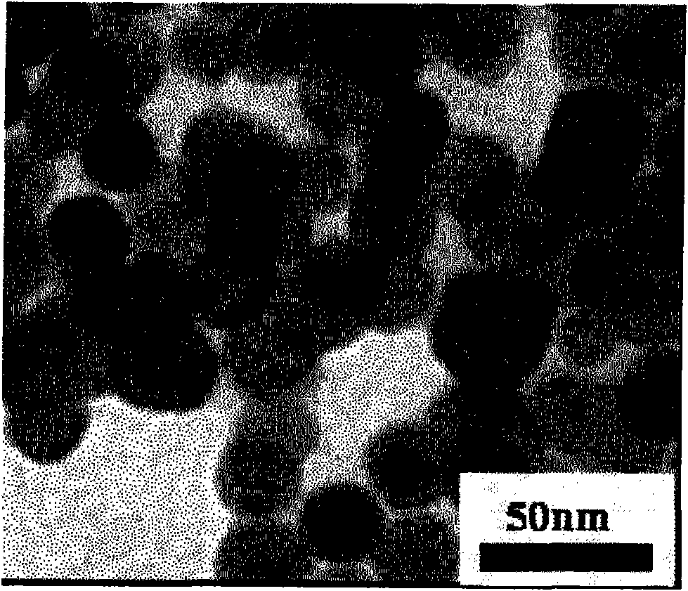
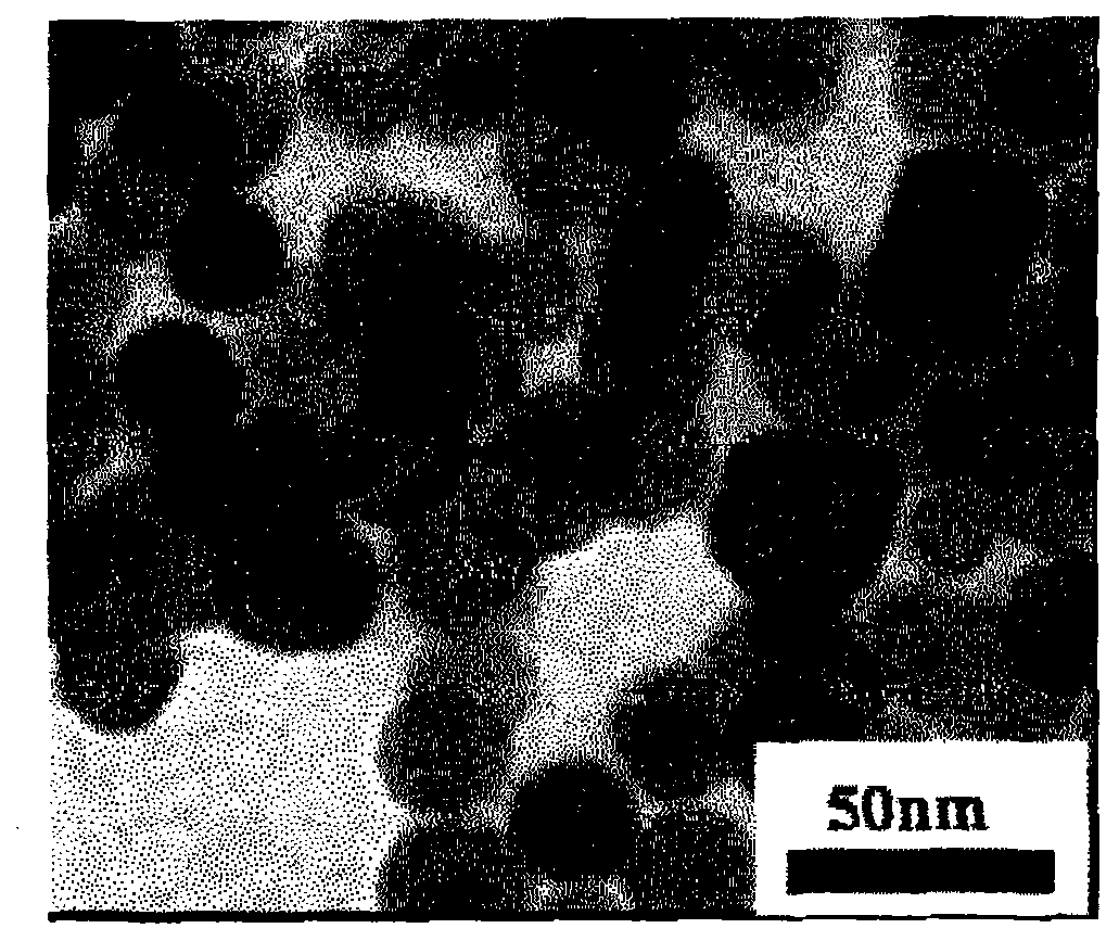
[0101] Coefficient of variation of particle diameter: Using a photograph taken by a transmission electron microscope (manufa...

example 1

[0105] According to CeO 2 , BaO and B 2 o 3 The mol% of the basis represents the amounts of 33.4%, 13.3% and 53.3% respectively. Weighing cerium oxide (CeO 2 ), barium carbonate (BaCO 3 ) and boron oxide (B 2 o 3 ), was sufficiently wet-mixed with an automatic mortar using a small amount of ethanol, and then dried to prepare a raw material mixture.

[0106] The obtained raw material mixture was filled in a platinum container (containing 10% by mass of rhodium) with a nozzle for dripping the melt, and heated at 1500° C. for 2 hours in an electric furnace using molybdenum silicide as a heating element to completely Melting (melting process). Next, the nozzle portion was heated, and the melt was dripped onto a double roll made of SUS316 (roll diameter: 150 mm, roll speed: 300 rpm, roll surface temperature: 30° C.) installed under the electric furnace to obtain a flake-shaped solid ( quenching process). The obtained flaky solid was transparent, and it was confirmed as an a...

example 2

[0114] CeO was obtained in the same manner as in Example 1, except that the time for heating the pulverized product was set to 32 hours. 2 crystal particles. The crystallite diameter of the obtained microparticles was 22 nm, the average primary particle diameter was 26 nm, the crystallite diameter:average primary particle diameter=1:1.2, and the variation coefficient of the particle diameter was 0.22.


PUM

PropertyMeasurementUnit
particle sizeaaaaaaaaaa

Abstract

Disclosed is a method for producing an oxide crystal fine particle which has high crystallinity and small particle diameter, while being excellent in uniformity of composition and particle diameter. Also disclosed is an oxide crystal fine particle. Specifically disclosed is a method for producing an oxide crystal fine particle, which is characterized by comprising, in the following order, a step for obtaining a molten material containing an oxide of M (M is one or more elements selected from the group consisting of Ce, Ti ,Zr, Al, Fe, Zn, Mn, Cu, Co, Ni, Bi, Pb, In, Sn and rare earth elements (excluding Ce)) and B2O3; a step for rapidly cooling the molten material into an amorphous material; a step for obtaining a pulverized powder having a volume-based particle size distribution of 0.1-40 [mu]m by pulverizing the amorphous material; a step for precipitating an oxide crystal containing M in pulverized particles by heating the pulverized powder; and a step for obtaining crystal fine particles of an oxide containing M by separating the components other than the oxide crystal containing M from the crystal precipitated particles.

Description

technical field [0001] The present invention relates to a method for producing oxide crystal fine particles, and more particularly to a method for easily obtaining oxide crystal fine particles having high crystallinity, excellent uniformity in composition and particle diameter, and small particle diameter, and the fine particles. Background technique [0002] In recent years, especially with the high integration and high functionality of semiconductor integrated circuits, the development of microfabrication technology for miniaturization and high density has been demanded. In the manufacturing process of semiconductor devices, especially in the process of forming multilayer lines, the planarization technology of interlayer insulating films and embedded lines is very important. That is to say, with the miniaturization and high-density of the semiconductor manufacturing process, the multi-layer circuit is easy to become larger. In order to prevent the height difference from ex...

Claims


Application Information

Patent Timeline
Patent Type & Authority Applications(China)
IPC IPC(8): C01F17/00C01B13/14C09K3/14C01F17/235
CPCC01G25/006C01P2002/60C09K3/1409C01P2004/51C01P2002/50C01P2004/61C01P2006/12C01F17/0043C01P2004/32C01P2004/64C01P2006/22C01P2006/10C09K3/1427C01P2004/04C01P2004/62B82Y30/00C01B13/14Y10T428/2982C01F17/235C01G25/02C01F17/224C01P2004/60
Inventor 酒井智弘别府义久铃木宏幸犬塚信夫
Owner ASAHI GLASS CO LTD
Learn More