Check patentability & draft patents in minutes with Patsnap Eureka AI!

Valve element and thermostatic control device for controlling a mass flow

A technology of constant temperature adjustment and quality adjustment, applied in the field of valve components, it can solve problems such as limitation, and achieve the effect of simple and fast matching

Inactive Publication Date: 2010-07-21
OTTO EGELHOF GMBH & CO KG
View PDF1 Cites 7 Cited by
  • Summary
  • Abstract
  • Description
  • Claims
  • Application Information

AI Technical Summary

Problems solved by technology

Furthermore, such return temperature limiting valves have the disadvantage that their use is limited to this particular application

Method used


Image

  • Valve element and thermostatic control device for controlling a mass flow
  • Valve element and thermostatic control device for controlling a mass flow
  • Valve element and thermostatic control device for controlling a mass flow

Examples


Embodiment Construction

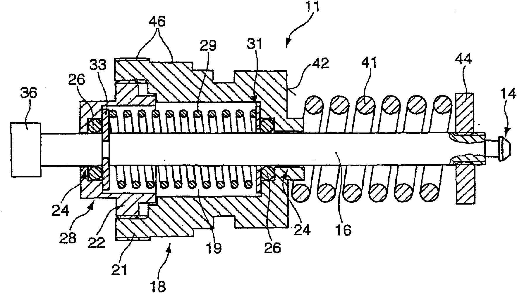
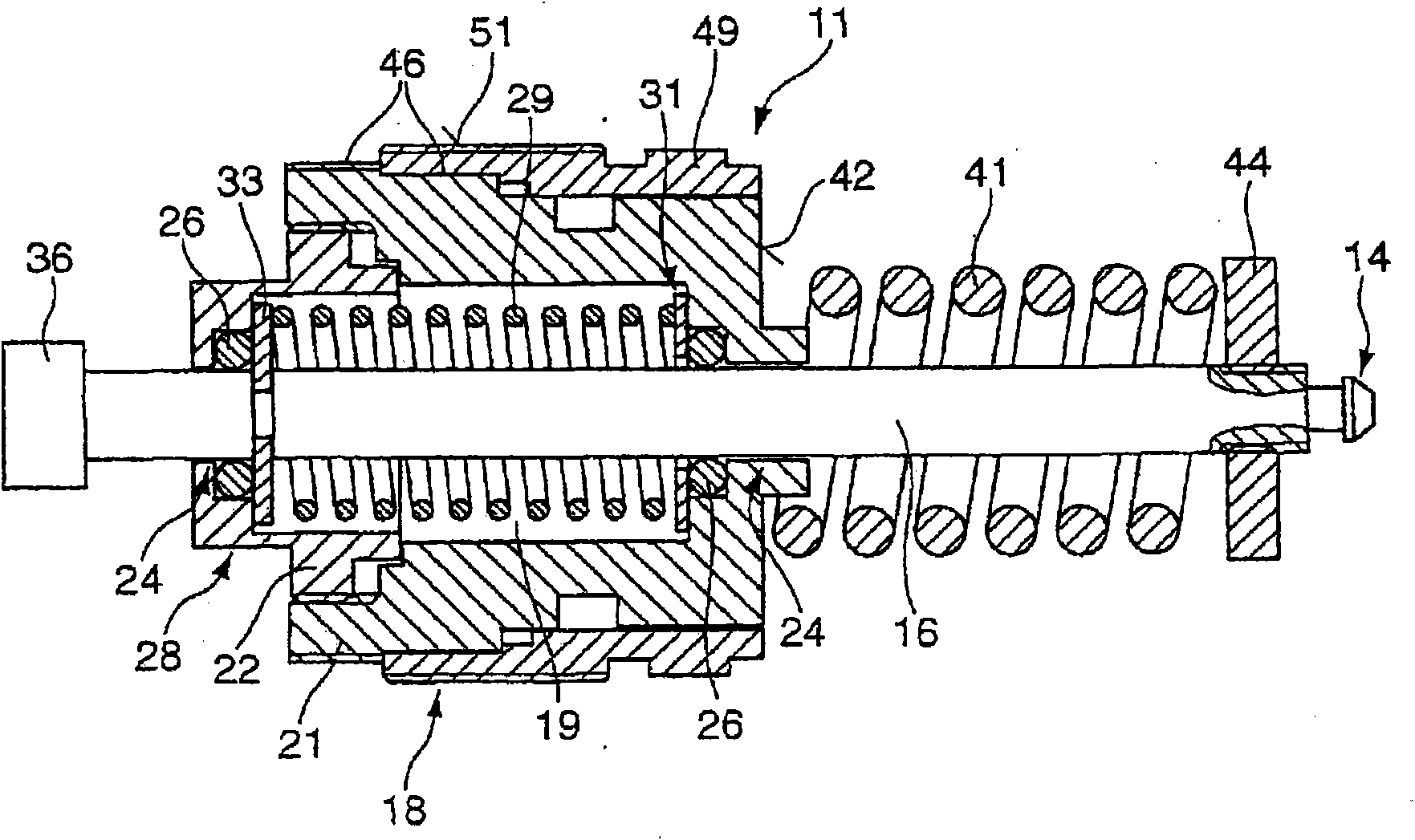
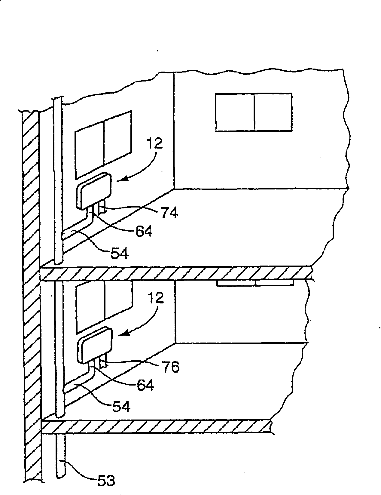
[0037] figure 1 A schematic cross-sectional view of the valve element 11 is shown in. This valve element 11 is preferably configured as a built-in cylinder and is set to be used in a thermostat 12, in image 3 The installation location of the thermostat 12 is shown and described in detail in Figure 4a to 4c The structure of the thermostat 12 is shown and described in detail.

[0038] The valve element 11 includes a valve closing member 14 which is movable relative to a valve seat in the thermostat 12 in order to adjust the mass flow. The valve closing member 14 includes, for example, a transfer pin 16 which is guided through the housing part 18 in an axially movable manner. Preferably, the transfer pin 16 passes through the cavity 19 in the housing part 18 and leads from the housing part 18 on the opposite side. The housing part 18 has a first part 21 preferably configured in a U-shape, and a second part 22, which are fixed to each other by a separable connection, in particula...


PUM


Abstract

The invention relates to a valve element for a thermostatic control device (12) and to a thermostatic control device for controlling a mass flow, having a valve closing member (14) which can be arranged in a valve seat (83) and which can be actuated by means of a transmission pin (16), having a housing section (18) in which the transmission pin (16) is guided at least in sections, and having at least one force store element (29) which is provided in the housing section (18) and which acts in a first movement direction such that the valve closing member (14) is arranged in an initial position (28) with respect to the housing section (18), wherein at least one thermal actuating member (41) composed of a shape-memory alloy engages both on the housing section (18) and also on the valve closing member (14) and has a direction of action opposite to the first movement direction and generates a temperature-dependent actuating movement of the valve closing member (14) counter to the at least one force store element (29), such that the actuating force of the thermal actuating member (41) is greater than that of the at least one force store element (29).

Description

Technical field [0001] The invention relates to a valve element and a constant temperature regulating device for regulating mass flow. Background technique [0002] DE 298 05 473 U1 discloses a thermostatic valve as a backflow limiter for floor heating systems, which thermostatic valve includes on the housing an inlet flow section and an outlet for the mass flow to be regulated. The inlet flow section is assigned to a through opening into the chamber, and a valve seat is constructed at the through opening so that the through opening can be closed by a valve closing member arranged in the valve seat. A spring is arranged in the chamber of the housing, which spring acts in the flow direction of the mass flow. The valve closing member is controlled by a body of expanded material. In this case, the expansion material body is a so-called wax expansion element containing paraffin wax. From a certain temperature, the aggregate state of the paraffin wax changes from a solid to a liqui...

Claims


Application Information

Patent Timeline
Patent Type & Authority Applications(China)
IPC IPC(8): G05D23/01G05D23/02E03C1/044
CPCF16K31/002G05D23/10F24D2220/0257F24D19/1015
Inventor J·索恩
Owner OTTO EGELHOF GMBH & CO KG
Features
  • R&D
  • Intellectual Property
  • Life Sciences
  • Materials
  • Tech Scout
  • Unparalleled Data Quality
  • Higher Quality Content
  • 60% Fewer Hallucinations
Learn More