Anchor positioning system for detecting planetoid lander

A positioning system and lander technology, applied in the field of deep space exploration and positioning systems, can solve the problems of the quality change of the moving part of the telescopic casing, the difficulty of estimating the initial launch energy, and the damage of the lander instrument, so as to save launch costs, light weight, Eliminates the effect of lateral shock loads

Inactive Publication Date: 2010-07-28
HARBIN INST OF TECH
View PDF2 Cites 47 Cited by
  • Summary
  • Abstract
  • Description
  • Claims
  • Application Information

AI Technical Summary

Problems solved by technology

[0018] The purpose of the present invention is to solve the problem that the telescopic casing connection and positioning system exists when the anchor tip is inclined during incidence, and the transverse impact load acts on the lander, causing damage to the internal instruments of the lander; and the mass of the moving part of the telescopic casing during the incident process change, presents a difficult problem in estimating initial launch energy, and provides an anchoring system for asteroid lander detection

Method used


Image

  • Anchor positioning system for detecting planetoid lander
  • Anchor positioning system for detecting planetoid lander
  • Anchor positioning system for detecting planetoid lander

Examples


specific Embodiment approach 1

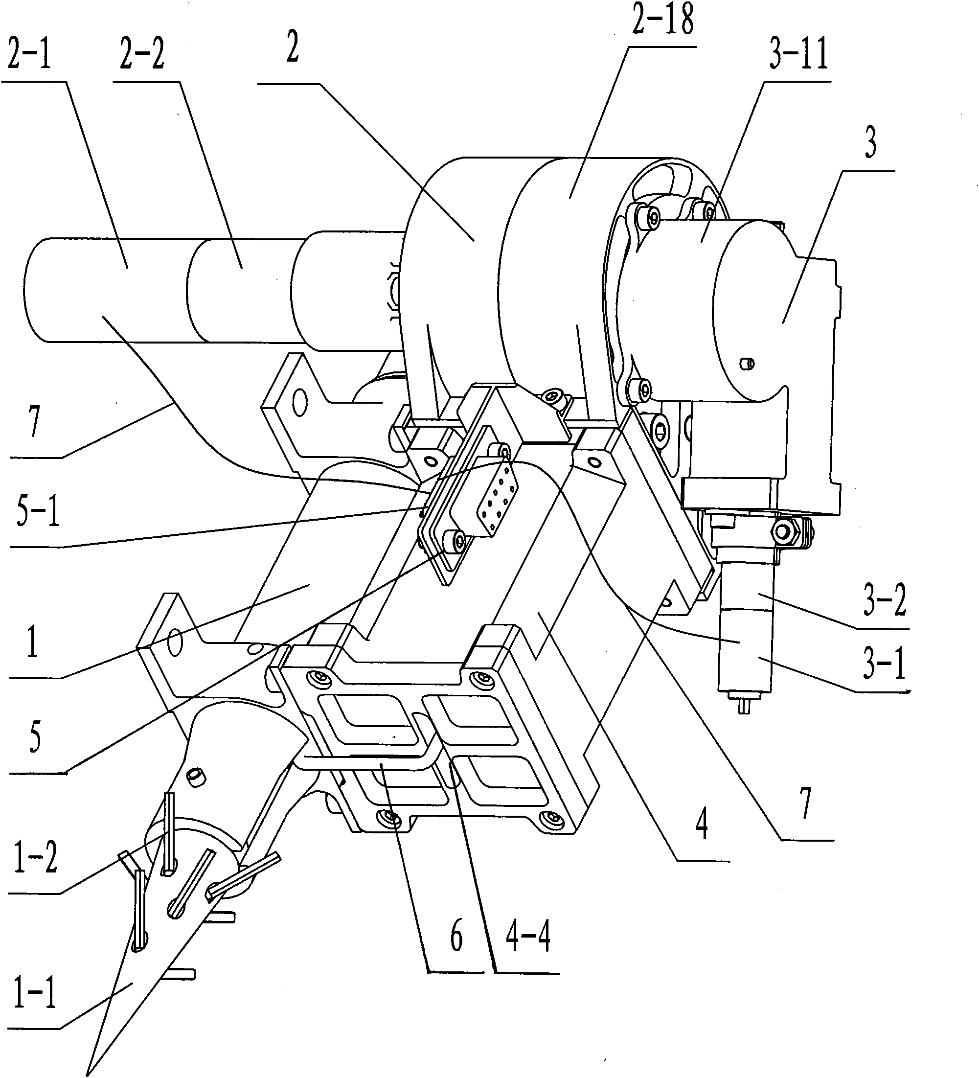
[0028] Specific implementation mode one: combine Figure 1-Figure 18 Describe this embodiment, the anchor positioning system for asteroid lander detection in this embodiment consists of a propulsion mechanism 1, a winding mechanism 2, a locking and unlocking mechanism 3, a cable box 4, an electrical interface 5, a connecting wire 6 and Composed of two wires 7;

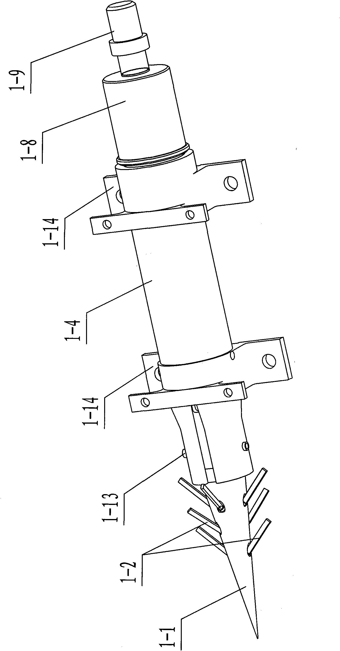
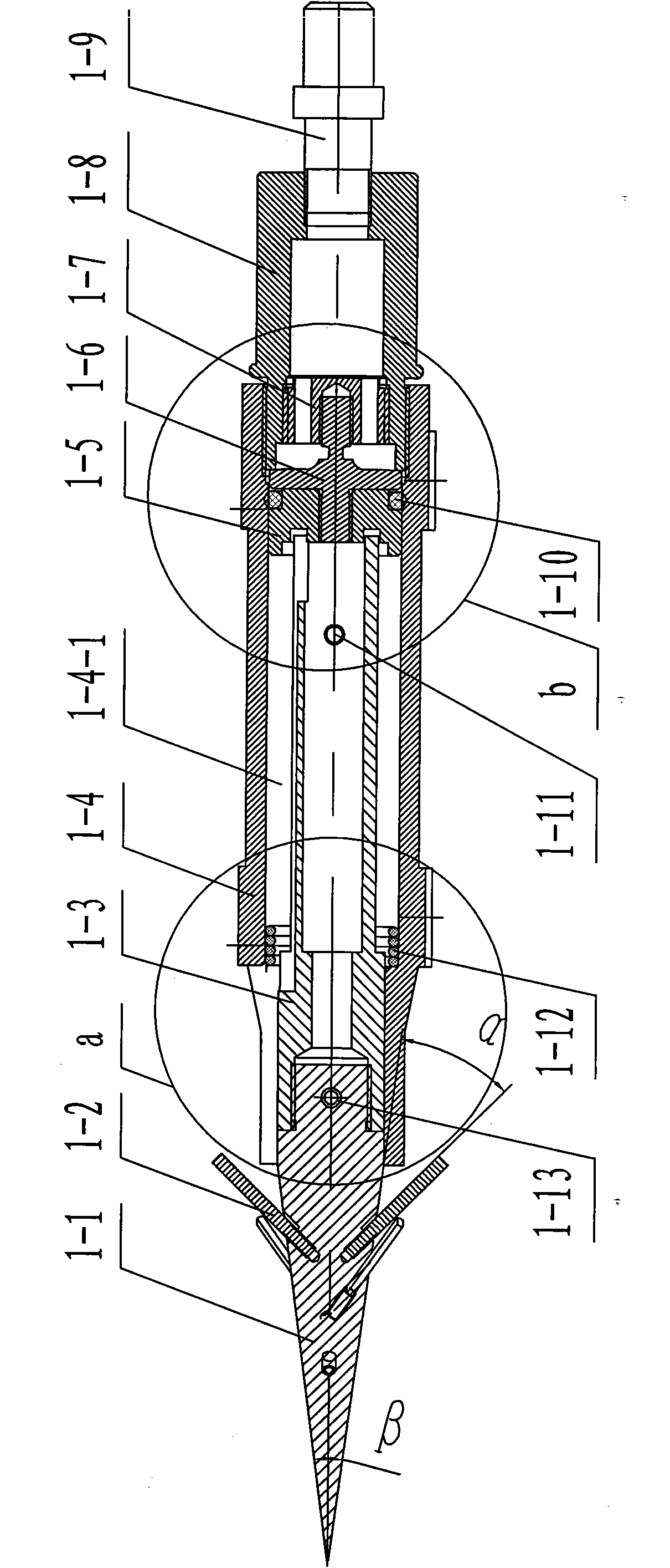
[0029] The propulsion mechanism 1 includes an anchor body, an expansion cylinder 1-4, a piston 1-5, a tear pin 1-6, a piston cap 1-7, a combustion chamber 1-8, an explosive device 1-9, and an anchor pin 1 -11. A signal detection sleeve 1-13 with wires and two link interfaces 1-14; the anchor body is composed of an anchor tip 1-1, a plurality of barbs 1-2 and an anchor rod 1-3, the The plurality of barbs 1-2 are evenly arranged on the outer wall of the anchor tip 1-1, the tail end of the anchor tip 1-1 is fixedly connected to one end of the anchor rod 1-3, and the piston 1-5 is arranged on the anchor rod 1 -3, one end...

specific Embodiment approach 2

[0035] Specific implementation mode two: combination image 3 The present embodiment will be described. The taper β of the anchor tip 1-1 of the present embodiment is 15°. With such a setting, it is convenient to shoot into the surface of the asteroid, and has a better penetration depth. Other compositions and connections are the same as in the first embodiment.

specific Embodiment approach 3

[0036] Specific implementation mode three: combination image 3 To describe this embodiment, the included angle α between the barb 1-2 and the generatrix of the anchor tip 1-1 in this embodiment is 10-20°. With such a setting, it is convenient to inject into the surface of the asteroid, and the adhesion is strong. Other compositions and connections are the same as those in Embodiment 1 or Embodiment 2.


PUM


Abstract

The invention relates to an anchor positioning system for detecting a lander, in particular to the anchor positioning system for detecting a planetoid lander. The anchor positioning system solves the following problems of a telescopic sleeve connecting and positioning system: an anchor bill is inclined when in incidence and transverse impact load is acted on the lander, so as to damage instruments at the inner part of the lander; a moving part of a telescopic sleeve is changed in quality during the incidence, so as to cause difficulty in estimating initial emission energy. An advancing mechanism is fixedly arranged on the side face of a cable box body, a winding mechanism is fixedly arranged on a rear end cover of the cable box body, a locking and unlocking mechanism is fixedly arranged on a right shell body of the winding mechanism, a connecting rope is stored in the cable box body, one end of the connecting rope is fixed on an anchor rod pin, and the other end of the connecting ropeis fixedly connected with a winding reel. A winding motor and an unlocking motor are connected with a pin socket by a lead wire. The anchor positioning system can also be used not only for detecting the lander of a small celestial body with weak surface gravitation such as the comet and the like, but also for automatic operation of a robot in dangerous environments.

Description

technical field [0001] The invention relates to an anchor positioning system for lander detection, belonging to the technical field of deep space detection and positioning systems. Background technique [0002] The development of space technology has made it possible for humans to send probes to some planets in the solar system, and land on the surface of some planets to retrieve soil and rock samples, and to understand and use planets through scientific experiments. So far, humans have landed on the surface of the moon and Mars, and successfully retrieved lunar soil and rock samples. In addition to the moon and Mars, humans have also launched landers to Venus, Jupiter, asteroids, and comets. With the advent of the 21st century, deep space exploration technology, as an important means for human beings to protect the earth, enter the universe and find new living homes, has attracted great attention from various countries in the world. Deep space exploration will be an impor...

Claims


Application Information

Patent Timeline
Patent Type & Authority Applications(China)
IPC IPC(8): B64G1/22B64G1/62
Inventor 赵志军赵京东刘伊威刘宏姜力张智
Owner HARBIN INST OF TECH
Why Eureka
Try Eureka