Tension-driving automatic wire-arranging mechanism

An automatic wiring and wire technology, which is applied in the direction of conveying filamentous materials, thin material handling, transportation and packaging, etc., can solve the problems of high labor intensity of workers, increase in the number of equipment sets, and high cost of equipment, so as to achieve low labor intensity of workers , Stable cable quality and low equipment cost

Inactive Publication Date: 2010-07-28
SHUNDE POLYTECHNIC
View PDF0 Cites 19 Cited by
  • Summary
  • Abstract
  • Description
  • Claims
  • Application Information

AI Technical Summary

Problems solved by technology

The manual cable arrangement method is neat, but there are disadvantages such as low efficiency, high labor intensity, and poor safety; the screw-driven cable arrangement mechanism requires that the pitch of the screw must be the same as the diameter of the cable to be arranged, but the actual situation is that there is an error in the diameter of the cable. There are many wire diameter specifications, and the error of the wire diameter will easily

Method used


Image

  • Tension-driving automatic wire-arranging mechanism
  • Tension-driving automatic wire-arranging mechanism
  • Tension-driving automatic wire-arranging mechanism

Examples


Example Embodiment

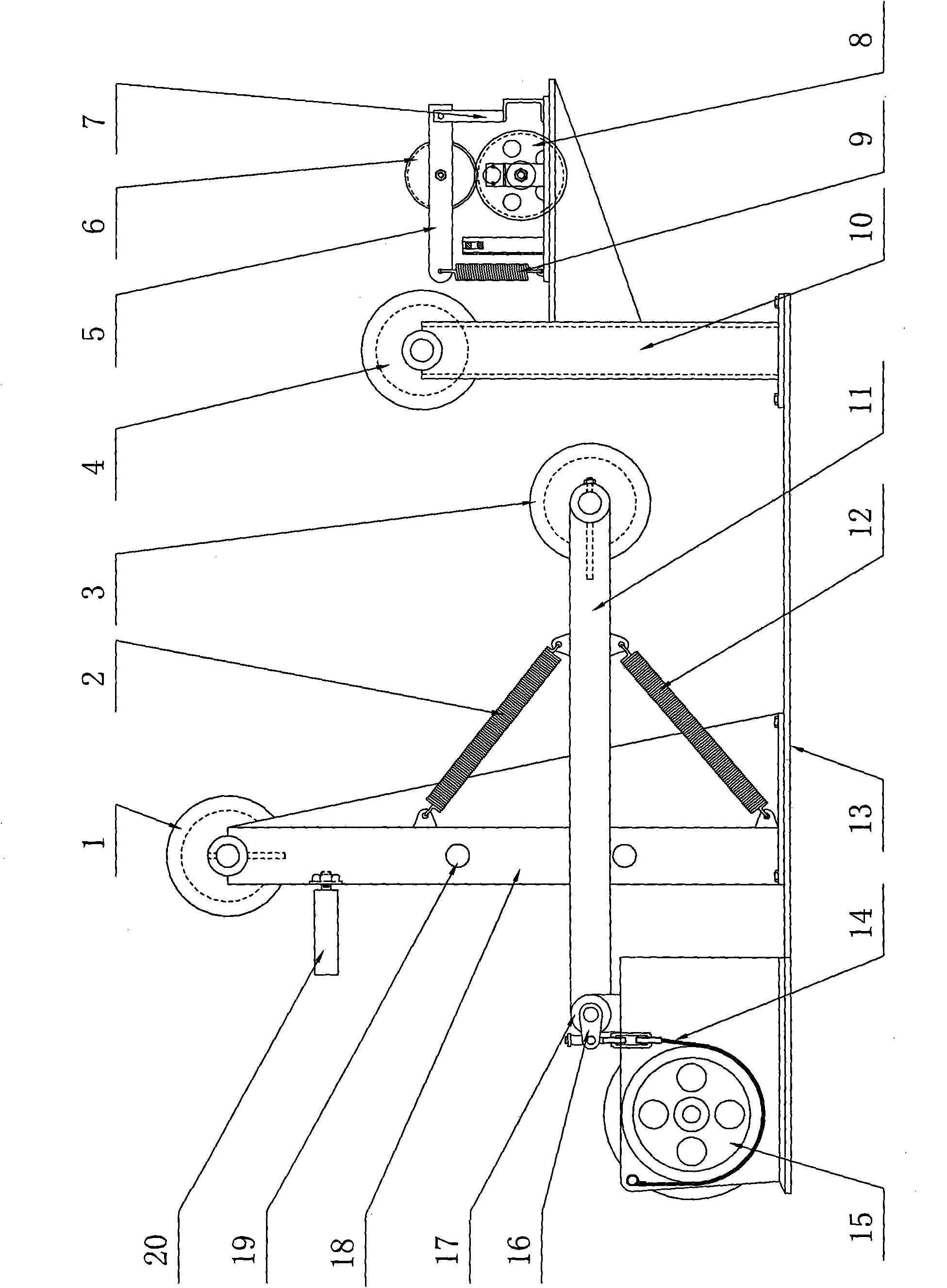
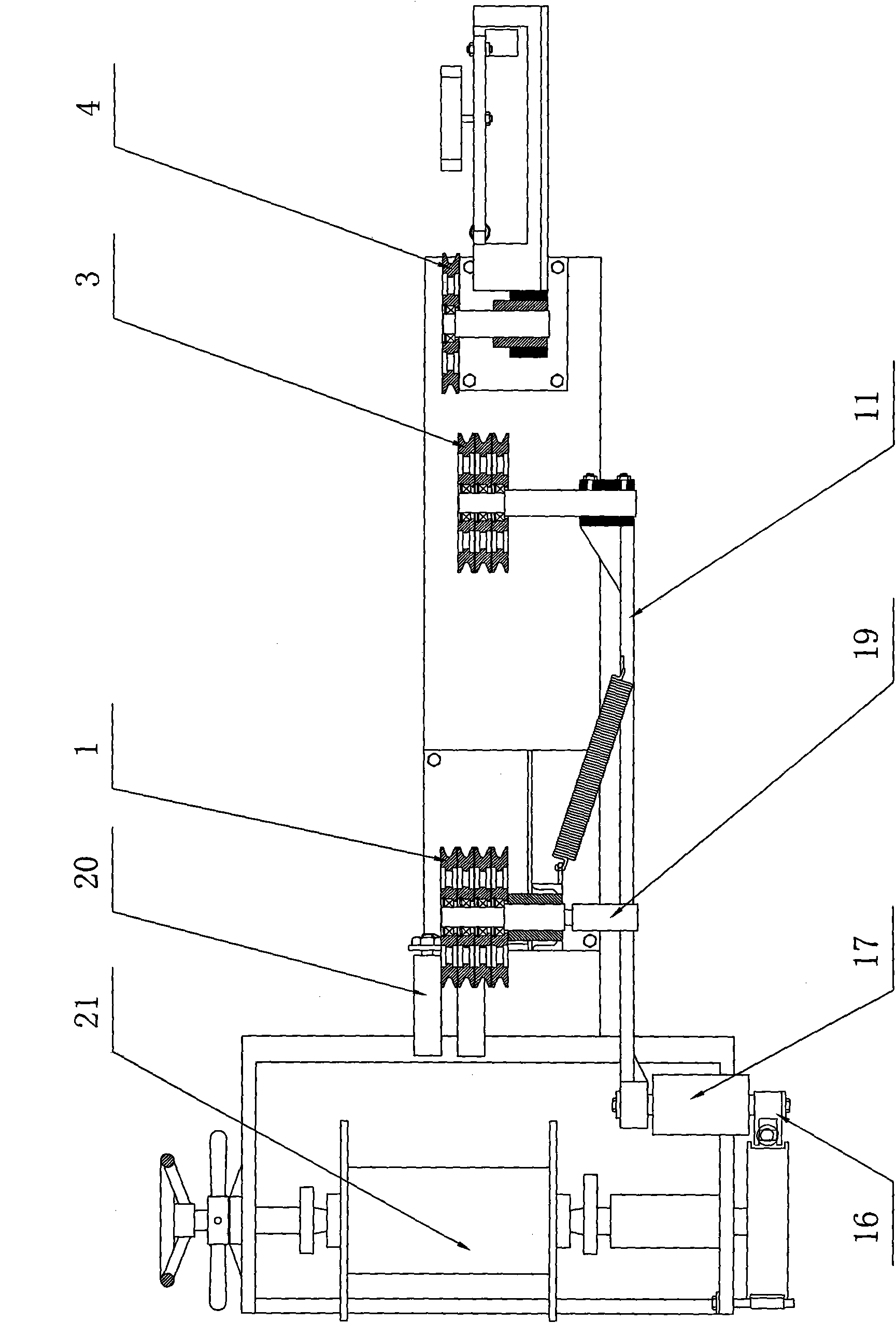
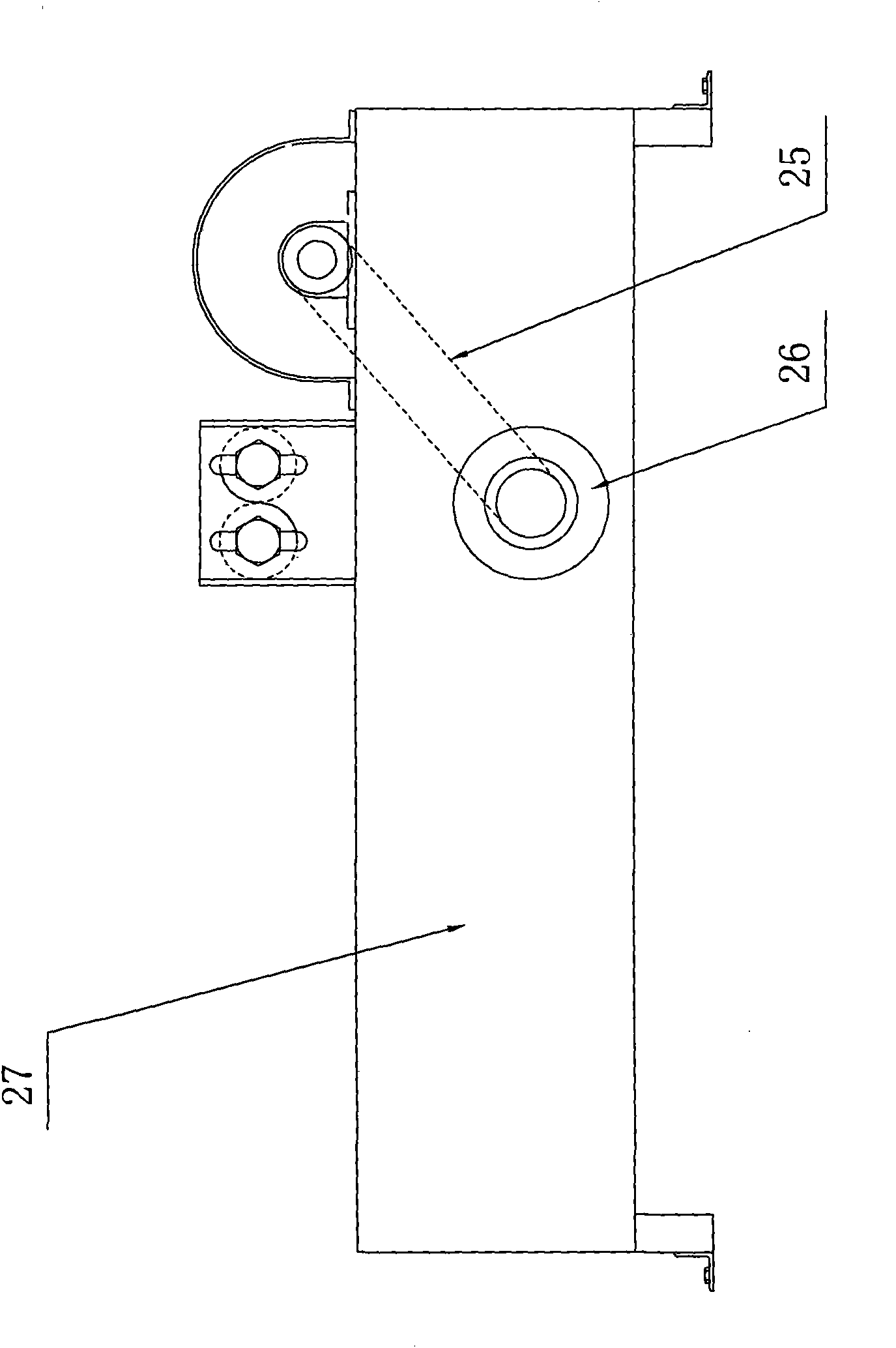
[0017] Below in conjunction with accompanying drawing and embodiment, the present invention will be described in further detail:

[0018] like Figures 1 to 4 As shown, it is a tension-driven wire automatic arranging mechanism, including a pay-off device and a loop-forming device, wherein the pay-off device includes a base 13, a floating guide wheel group 3, a pay-off frame 21, The fixed guide wheel group bracket 18 and the guide wheel bracket 10, the fixed guide wheel group 1 arranged on the fixed guide wheel group bracket, and the guide wheel 3 arranged on the guide wheel bracket; The motor 26 on the electric box, the ring-forming disc 24 driven by the motor; the fixed guide wheel group 1 is composed of four guide wheels connected in series coaxially, and the four guide wheels can rotate freely; the floating guide wheel group 3 is composed of the same The shaft is composed of three guide wheels connected in series, and the three guide wheels can rotate freely. The feature ...


PUM


Abstract

The invention discloses a tension-driving automatic wire-arranging mechanism, comprising a pay-off device and a loop-forming device, wherein the pay-off device comprises a base, a floating guide wheel set, a pay-off frame and a fixed guide wheel set bracket and a guide wheel bracket which are arranged on the base, a fixed guide wheel set arranged at the fixed guide wheel set bracket, and a guide wheel and a crossing-wire wheel which are arranged at the guide wheel bracket; the loop-forming device comprises a transmission electric box, an electric motor arranged at the transmission electric box, and a loop-forming plate driven by the electric motor. The invention is characterized in that the paying-off device also comprises a brake wheel arranged on the base and a brake belt matched with the brake wheel, a level mechanism and a lever rotating shaft, an elastic supporting device for supporting the lever mechanism, two guide shafts arranged on the transmission electric box, and two wire-arranging guide wheels which are respectively arranged on the guide wheel shafts and can slide and rotate; the brake wheel is coaxial to the pay-off frame, one end of the brake belt is fixed on the base and the other end is connected with the left end of the lever mechanism, and the floating guide wheel set is arranged at the right end of the lever mechanism. The invention has the advantages of high efficiency, small labor intensity, good safety, stable wire-arranging quality and low cost.

Description

technical field [0001] The invention relates to a tension-driven wire automatic arranging mechanism. Background technique [0002] The traditional wire arranging mechanism mainly has two ways: manual arranging and screw drive driving arranging. The manual wiring method arranges the wires neatly, but there are disadvantages such as low efficiency, high labor intensity of workers, and poor safety; the screw-driven wiring mechanism requires that the pitch of the screw must be the same as the diameter of the wire to be discharged, but the actual situation is that there is an error in the diameter of the wire If there are many wire diameters and specifications, errors in the wire diameter will easily cause the cables to be irregular. If the wire diameters are too large, a screw drive device of the corresponding size needs to be equipped according to the wire diameter, resulting in an increase in the number of sets of equipment and a corresponding increase in the number of equipme...

Claims


Application Information

Patent Timeline
IPC IPC(8): B65H54/02B65H54/28B65H57/14B65H59/06B65H59/10B65H61/00
Inventor 覃岭陈学峰孔宇青许中明胡建国
Owner SHUNDE POLYTECHNIC
Why Eureka
Try Eureka