Gas laser

A gas laser and gas storage chamber technology, applied in the field of lasers, can solve the problems of high operating noise, large gas consumption, high use and maintenance costs, and achieve the effects of processing accuracy requirements, high installation accuracy, improved output power, and guaranteed stability.

Inactive Publication Date: 2012-06-20
HUAZHONG UNIV OF SCI & TECH
View PDF0 Cites 0 Cited by
  • Summary
  • Abstract
  • Description
  • Claims
  • Application Information

AI Technical Summary

Problems solved by technology

[0002] At present, the market potential of medium-power (hundreds of watts to kilowatts) lasers is huge. Up to now, there is no practical product that users are very satisfied with. The discharge area of ​​the glass tube laser, because the discharge area is too long, the excitation voltage is too high, and it is inconvenient to transport, install, and use; the second solution is to use a folded optical path structure of multiple discharge tubes, which increases the optical lens. It also increases the complexity of the system, reduces the stability of the optical path and the stability and reliability of the laser output
For high-power lasers, fast-flowing gas excitation can be used to make cross-flow or axial-flow lasers, and the gas flow and cooling system are added, resulting in bulky size, heavy weight, high operating noise, large gas consumption, and high operating costs.
In order to solve this situation, a radio frequency excitation diffusion cooling slab laser has been designed abroad. The discharge electrode is a metal electrode with a water cooling channel. The distance between the electrodes is small. It is a waveguide structure for optical transmission, so the processing and installation of the electrodes are very complicated. The discharge chamber is a sealed container with a metal structure. The power supply is a radio frequency power supply. The output beam of the laser is a strip-shaped spot, which needs to be shaped before it can be used. This kind of laser has good performance and long life, but its technical difficulty is high, and the cost of equipment procurement and maintenance is high. , for a 100-watt laser with the same power, the price of the RF-excited slab laser is 10 times that of the sealed glass tube laser, so it is difficult to widely promote and apply it in our country

Method used


Image

  • Gas laser
  • Gas laser
  • Gas laser

Examples


Embodiment Construction

[0022] Below in conjunction with accompanying drawing and example the present invention is described in further detail.

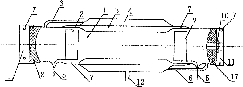
[0023] Such as figure 1 As shown, the gas laser provided by the present invention includes a discharge cavity 1, a discharge electrode 2, a water cooling channel 3, a gas storage chamber 4, a strip reflector 8 at the tail mirror end, a strip reflector 9 at the output end and a fully transparent output mirror 10.

[0024] The discharge chamber 1 is made of non-metal such as glass or ceramics. The discharge electrodes 2 are located at the front and rear ends of the discharge chamber 1, or on the left and right sides, and are connected to the electrode wires 5. The electrode wires 5 are respectively connected to external electrodes. The power supply is connected, and the power supply can use a common DC power supply instead of an RF power supply. The water-cooling channel 3 is distributed outside the discharge chamber 1, which can cool the area where the dis...


PUM


Abstract

The invention discloses a gas laser, which comprises a discharge chamber, a discharge electrode, a water-cooling channel and a gas storage chamber, wherein the water-cooling channel is distributed on the ektexine of the discharge chamber, the gas storage chamber is positioned outside the water-cooling channel, the discharge chamber and the gas storage chamber are communicated through a muffler, the discharge chamber is a sealed cavity which consists of a discharge cavity, a strip-shaped reflector on a tail end mirror, a strip-shaped reflector on an output end and a full-through output mirror,the discharge cavity is in a lath-shaped hollow-core structure which is made of nonmetal materials, the tail end mirror, the strip-shaped reflector on the output end are respectively positioned on the front end and the rear end of the discharge cavity, an aperture is left on the middle or one side of the strip-shaped reflector of the output end, the full-through output mirror is positioned at theposition of the aperture and is used as a laser output window, and the discharge electrode is poisoned in the front end and rear end of the discharge cavity, or in the left side and the right side ofthe discharge cavity. The gas laser has small size, light weight, simple structure, a cooling system with good cooling effect, high output power and stable laser beam with good mode, and can be used for the laser processing industry.

Description

technical field [0001] The invention belongs to laser technology, in particular to a gas laser, which is mainly used in the lath-shaped discharge area in the laser processing industry. Background technique [0002] At present, the market potential of medium-power (hundreds of watts to kilowatts) lasers is huge. Up to now, there is no practical product that users are very satisfied with. The discharge area of ​​the glass tube laser, because the discharge area is too long, the excitation voltage is too high, and it is inconvenient to transport, install, and use; the second solution is to use a folded optical path structure of multiple discharge tubes, which increases the optical lens. It also increases the complexity of the system, reduces the stability of the optical path and the stability and reliability of the laser output. For high-power lasers, fast-flowing gas excitation can be used to make cross-flow or axial-flow lasers, and the gas flow and cooling system are added. ...

Claims


Application Information

Patent Timeline
Patent Type & Authority Patents(China)
IPC IPC(8): H01S3/22H01S3/038H01S3/034H01S3/041
CPCH01S3/03H01S3/041
Inventor 秦应雄张本王度罗钦唐霞辉李波柳娟彭浩邓前松肖瑜
Owner HUAZHONG UNIV OF SCI & TECH
Why Eureka
Try Eureka