Ultrastrong damping high-voltage synchronous motor

A synchronous generator and generator stator technology, which is applied in the fields of synchronous generators and high-voltage synchronous generators, can solve the voltage waveform distortion at the terminals of high-voltage synchronous generators, restrict the load capacity of the generator, and the poor ability to carry non-linear loads, etc. problems, to achieve the effect of suppressing harmonics, improving dynamic performance, reducing surface loss, and improving response speed

Active Publication Date: 2010-07-28
ZHENJIANG ZHONGCHUAN XIANDAI GENERATING EQUIP CO LTD
View PDF4 Cites 4 Cited by
  • Summary
  • Abstract
  • Description
  • Claims
  • Application Information

AI Technical Summary

Problems solved by technology

[0004] With the development of science and technology, modern non-linear loads such as rectifiers and frequency converters in land, marine and offshore oil platforms are increasing, and these non-linear loads contain a large number of harmonic components, which have a great impact on the high-voltage synchronous The waveform of the terminal voltage of the generator causes serious distortion, which causes the effective capacity of the generator to drop and cannot be used normally. In serious cases, the generator will trip when it is under load.
Traditional high-voltage synchronous generators have poor ability to carry nonlinear loads. Currently, the best-performing synchronous generators can only carry nonlinear loads equivalent to about 30% of the rated capacity of the generator, which greatly restricts the load capacity of the generator. , so a high-voltage synchronous generator with stronger nonlinear load capacity is needed to meet the needs of the above applications

Method used


Image

  • Ultrastrong damping high-voltage synchronous motor
  • Ultrastrong damping high-voltage synchronous motor
  • Ultrastrong damping high-voltage synchronous motor

Examples


Embodiment Construction

[0015] The present invention will be further described below in conjunction with drawings and embodiments.

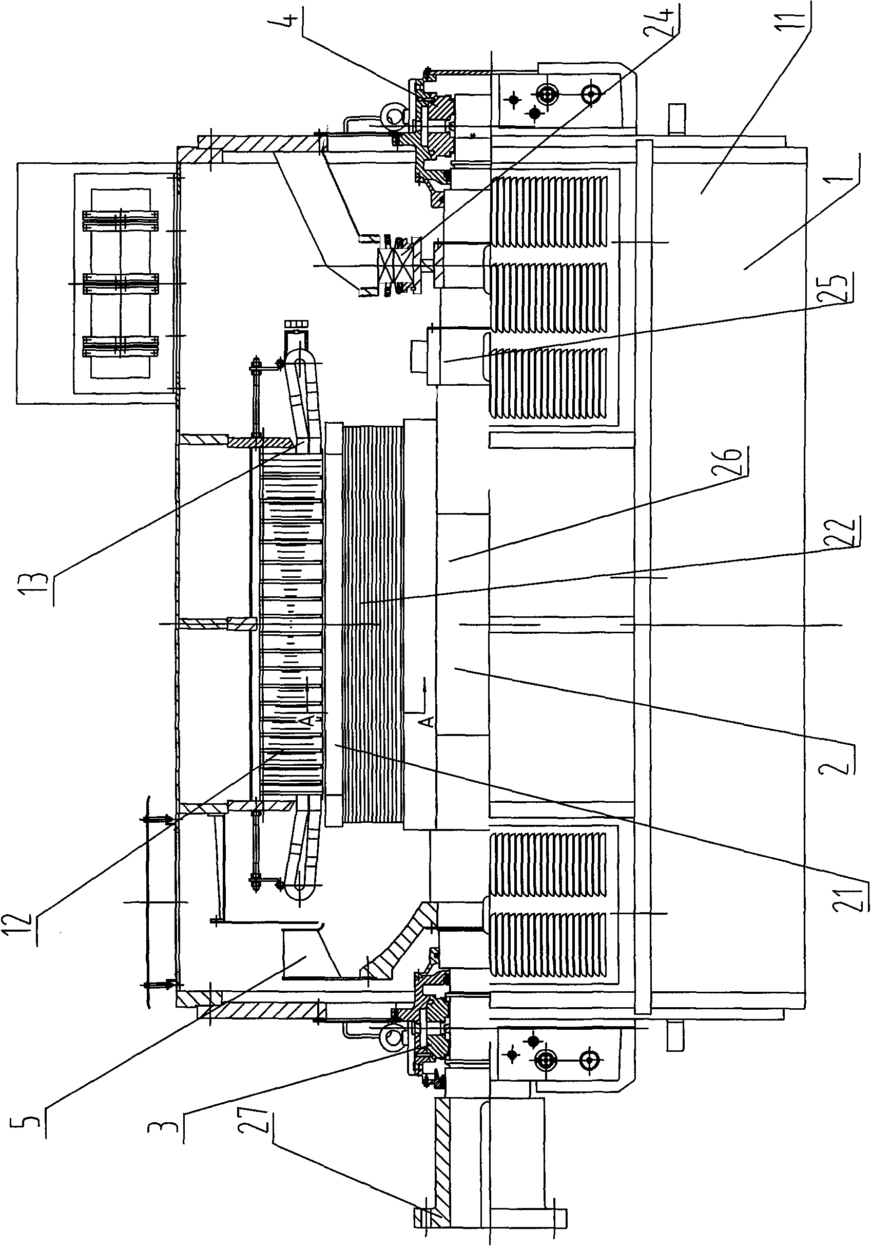
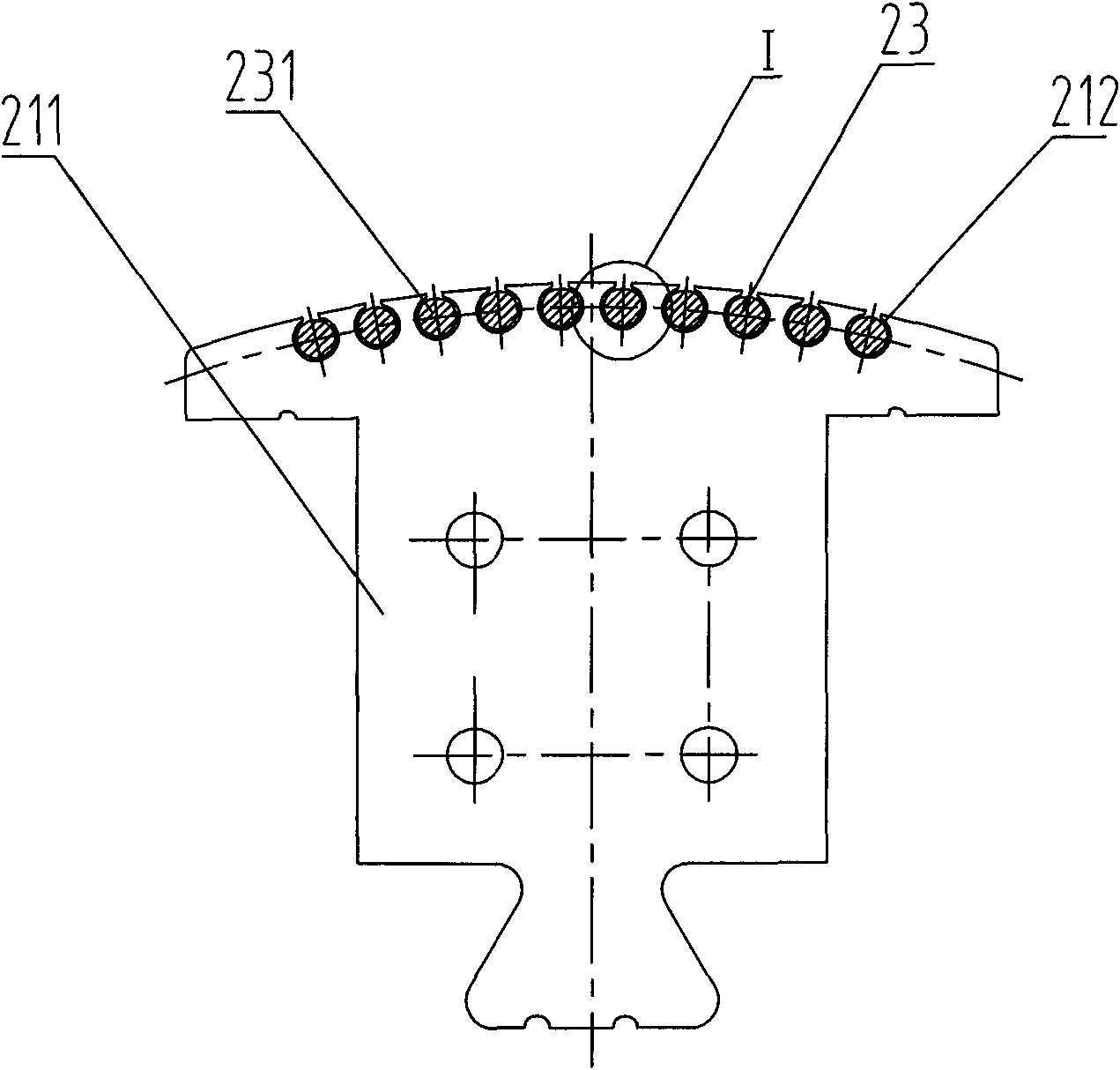
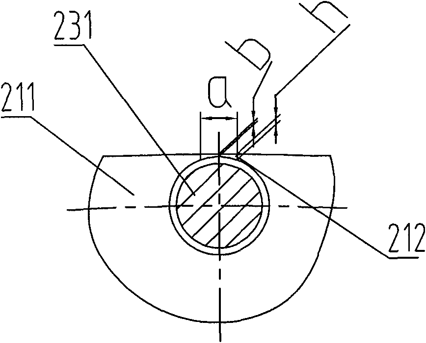
[0016] like Figure 1 ~ Figure 3 As shown, the present invention comprises generator stator 1, generator rotor 2, and generator stator 1 comprises frame 11, iron core 12 and stator coil 13; Generator rotor 2 comprises magnetic pole core 21, magnetic pole coil 22, damping winding 23, AC The exciter rotor 24, the rotary rectifier 25 and the rotating shaft 26, the two ends of the rotating shaft 26 are respectively supported on the base 11 through the shaft extension end bearing 3 and the non-shaft extension end bearing 4, and the shaft extension end of the rotating shaft 26 is equipped with a The semi-coupling 27 connected to the motor, the magnetic pole coil 22 is sleeved outside the magnetic pole core 21. A heat dissipation fan 5 is also installed at the shaft extension bearing 3 of the rotating shaft 26, and an AC exciter rotor 6 is installed at the non-shaft extension...


PUM


Abstract

The invention discloses an ultrastrong damping high-voltage synchronous motor which comprises a generator stator and a generator rotor, wherein the generator stator comprises a stand, an iron core and a rotor coil, and the generator rotor comprises a magnetic pole iron core, magnetic pole coils, an ultrastrong damping winding, an alternating current exciter rotor, a rotating rectifier and a rotating shaft; and a plurality of magnetic pole coils form a complete magnetic pole winding, a plurality of axial damping slotted holes are uniformly distributed at the radial periphery of the magnetic pole iron core, a plurality of damping winding copper rods respectively penetrates into each damping slotted hole of the magnetic pole iron core, and both ends thereof are respectively welded with a damping ring to form a cage-shaped whole. The width a of a damping hole notch on the magnetic pole iron core is 6-8mm, the depth h is 0.5-1mm, and the distance b to a magnetic pole surface is 0.4-0.5mm. The damping winding of the invention has ultrastrong damping effect, so that the harmonic inhabiting capability and the dynamic performance of the invention are greatly enhanced, thereby greatly improving the capability of carrying nonlinear loads.

Description

technical field [0001] The invention relates to a synchronous generator, in particular to a high-voltage synchronous generator capable of driving relatively nonlinear loads, and belongs to the technical field of motor manufacturing. Background technique [0002] High-voltage synchronous generators are widely used in the field of electric power and energy to provide power supplies of different power and voltage levels for various equipment loads. The high-voltage synchronous generator is mainly divided into two parts: the stator and the rotor. The stator includes the machine base, the stator core and the stator coil. The stator coil is embedded in the slot of the stator core according to a certain arrangement rule, and a complete three-phase stator is formed by proper connection. winding. The rotor includes pole cores, pole coils, damping windings, AC exciter rotors, rotary rectifiers (for brushless excitation) and shafts. Frequency and rotational speed decision) coils are ...

Claims


Application Information

Patent Timeline
Patent Type & Authority Applications(China)
IPC IPC(8): H02K19/16H02K1/26H02K3/04
Inventor 甘佐军吴登林姚立元张茂玲方甫根
Owner ZHENJIANG ZHONGCHUAN XIANDAI GENERATING EQUIP CO LTD
Why Eureka
Try Eureka