

Drive circuit capable of quickly switching off depletion type switching element
A technology of depletion switches and switching devices, which is applied in the direction of instruments, electrical components, and adjustment of electrical variables, etc., to speed up the turn-on speed, ensure reliability, and solve the effects of fast turn-on and fast turn-off
- Summary
- Abstract
- Description
- Claims
- Application Information
AI Technical Summary
Problems solved by technology
Method used
Image

Examples
Embodiment 1
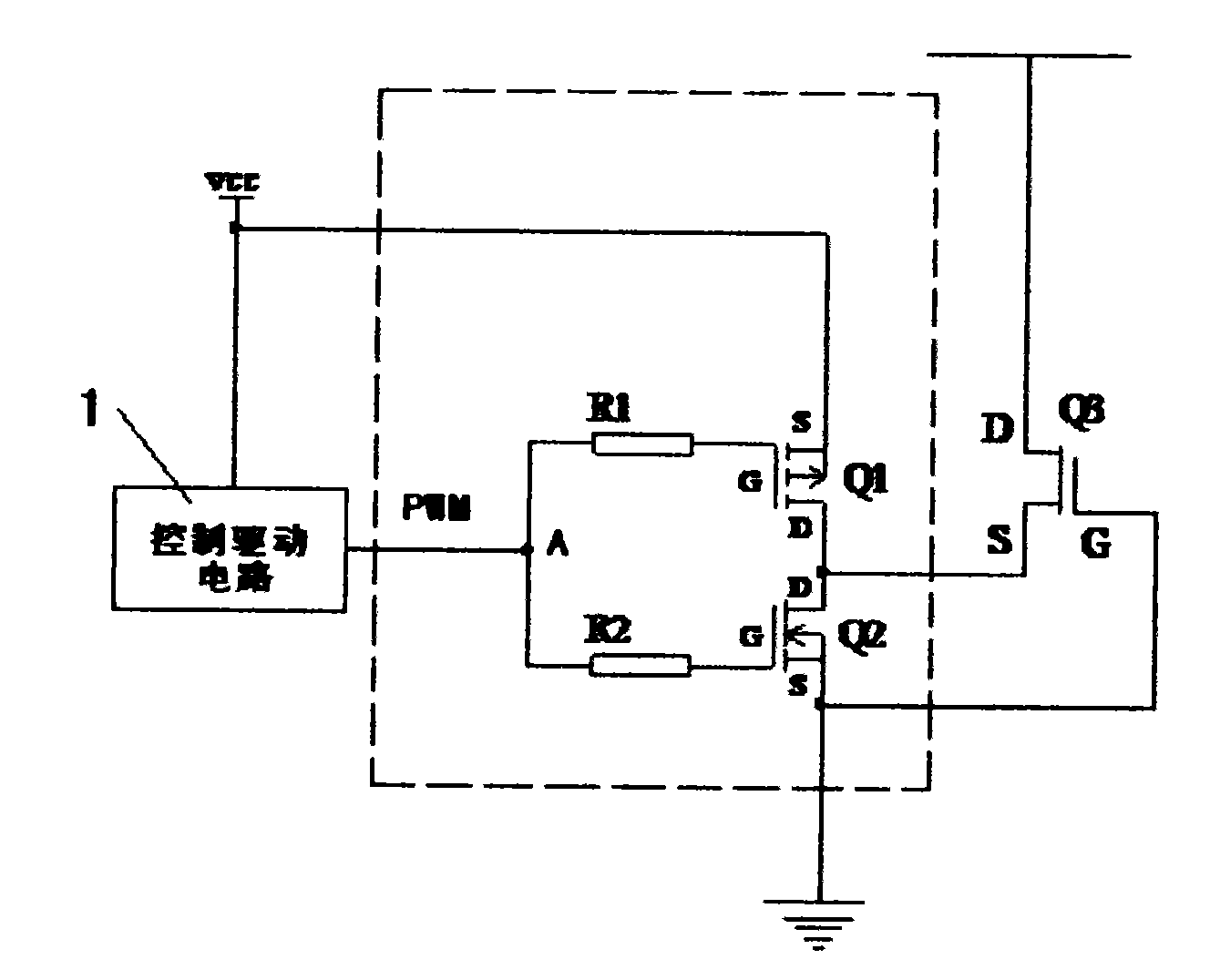
[0017] see figure 1 , the drive circuit consists of a P-channel enhanced switching device Q1 (hereinafter referred to as P-channel device) and an N-channel enhanced switching device Q2 (hereinafter referred to as N-channel device) and connected to the gates of the two switching devices Composed of resistors R1 and R2, the drain D of the P-channel device Q1 is connected to the drain D of the N-channel device Q2, and the source S of the P-channel device Q1 is directly connected to the power supply VCC of the driving circuit , the source S of the N-channel device Q2 is connected to the reference ground, the gate G of the P-channel device Q1 is connected to the drive control signal input terminal A through its gate resistor R1, and the gate of the N-channel device Q2 is connected through Its gate resistor R2 is connected to the drive control signal input terminal A, and the control signal input terminal A is connected to the signal output terminal of the external control drive cir...
Embodiment 2
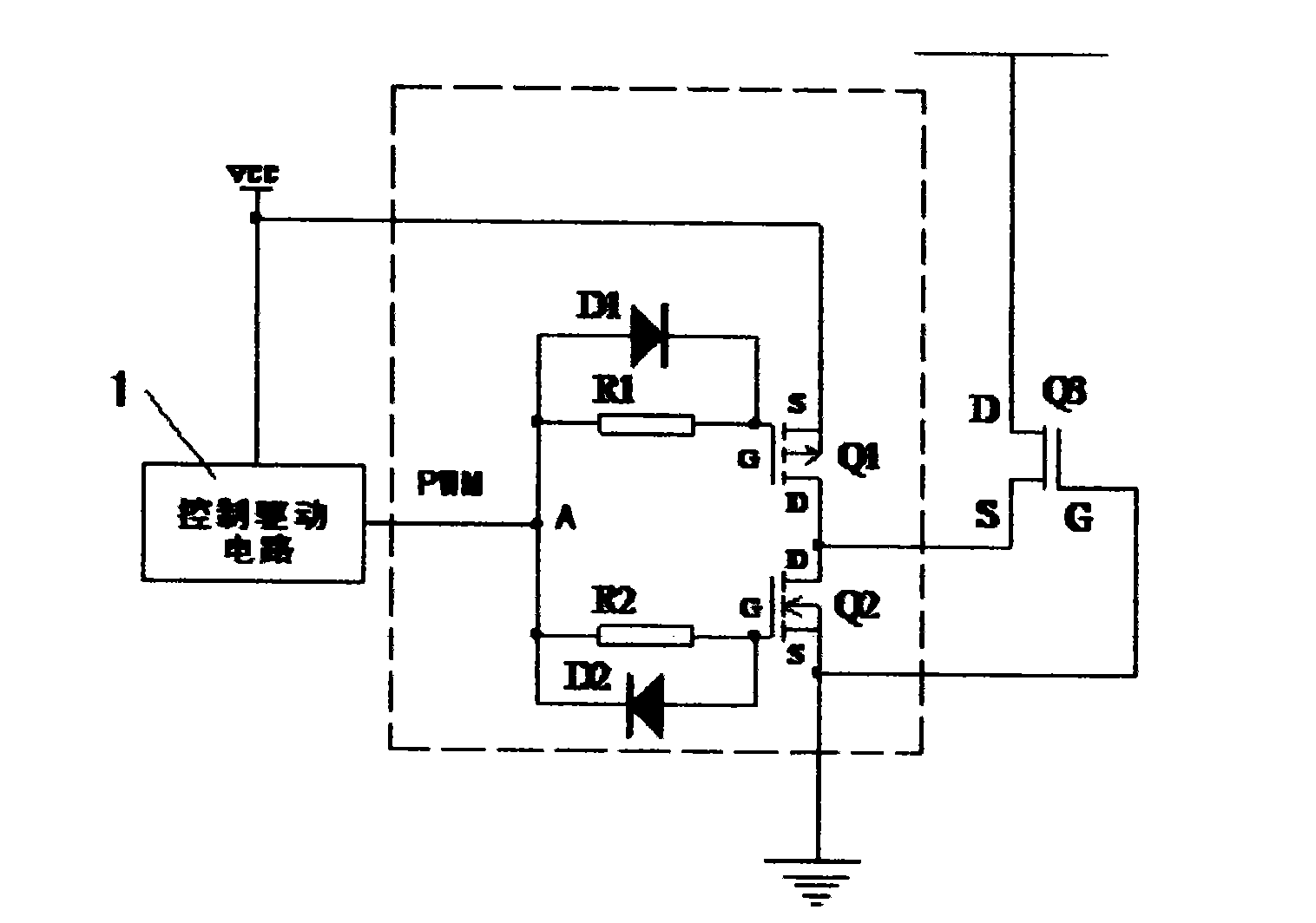
[0021] see figure 2 In this example, on the basis of Embodiment 1, a diode D1 is connected in parallel on the gate resistor R1 of the P-channel enhanced switching device Q1, and the cathode of the diode D1 is connected to the gate of the P-channel enhanced switching device Q1. , the anode of which is connected to the input terminal A of the control signal, another diode D2 is connected in parallel on the gate resistor R2 of the N-channel enhanced switching device Q2, and the anode of the diode D2 is connected to the N-channel enhanced switching device Q2 The gate of the grid is connected, and its cathode is connected to the input terminal A of the control signal.
[0022] Its working principle is: when the control drive circuit 1 outputs a high level, the diode D1 is turned on, and the high level signal is quickly added to the gate of the P-channel device Q1 through the diode D1, so that Q1 is quickly cut off; at the same time, When the diode D2 is turned off, the high-level...
Embodiment 3
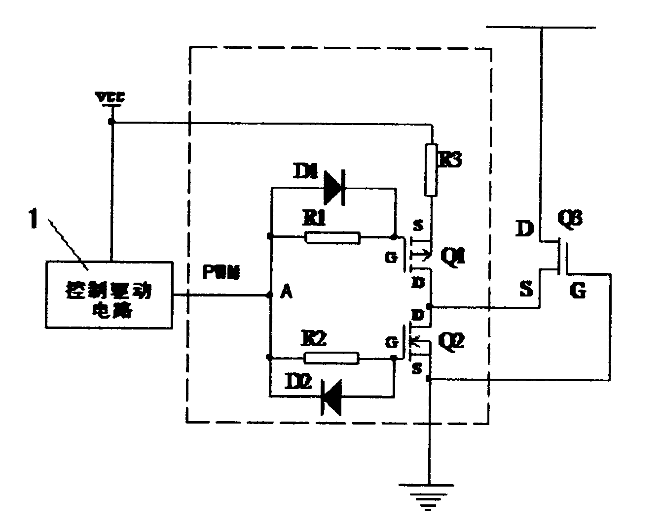
[0026] see image 3 , in order to further improve the safety and reliability of the driving circuit, a current limiting resistor R3 is connected in series with the source of the P-channel enhanced switching device Q1 to limit the maximum current flowing through the switching device Q1.
PUM
 Abstract
Description
Claims
Application Information