
Denitration system in favor of blowing deposited ash and catalyst arrangement method of denitration system

A technology of catalyst and soot blowing device, which is applied to chemical instruments and methods, separation methods, and separation of dispersed particles, etc., to achieve the effects of reducing wear, reducing clogging, and improving service life

Active Publication Date: 2010-08-04
CPI YUANDA ENVIRONMENTAL PROTECTION ENG
View PDF0 Cites 5 Cited by
  • Summary
  • Abstract
  • Description
  • Claims
  • Application Information

AI Technical Summary

Problems solved by technology

[0004]The problem with this method is: under the action of the soot blower, the ash can only be discharged from the inner pores of the catalyst. Since the inner pores of the catalyst are less, usually Between 6-10mm, due to the uneven flow rate and distribution of the flue gas, some ash with a large volume (close to or larger than the diameter of the inner hole of the catalyst) cannot pass through the catalyst smoothly, causing blockage. The longer the time, the more serious the blockage will be. Affect the removal efficiency of the catalyst

Method used


Image

  • Denitration system in favor of blowing deposited ash and catalyst arrangement method of denitration system
  • Denitration system in favor of blowing deposited ash and catalyst arrangement method of denitration system
  • Denitration system in favor of blowing deposited ash and catalyst arrangement method of denitration system

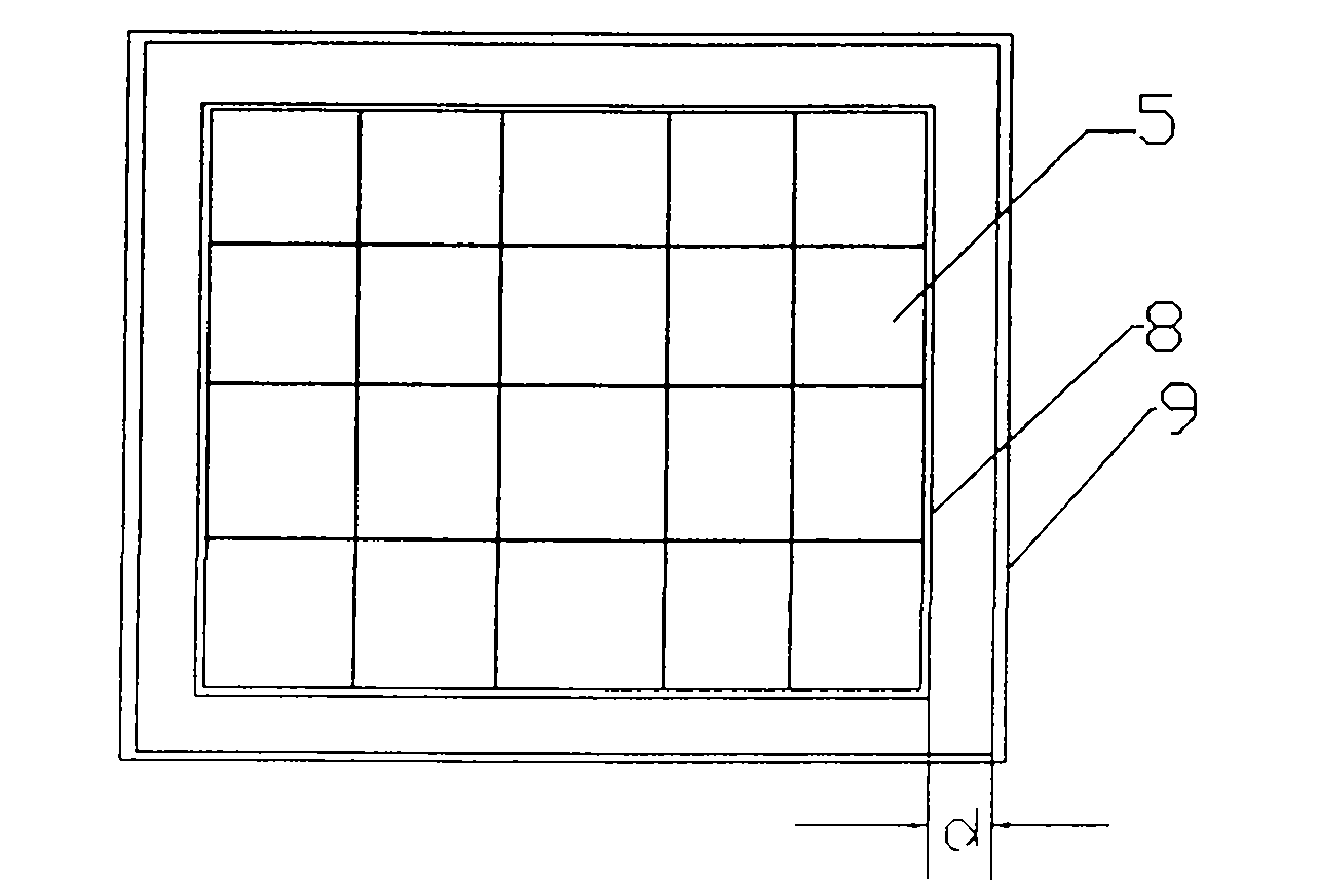
Examples


Embodiment Construction

[0023] Hereinafter, preferred embodiments of the present invention will be described in detail with reference to the accompanying drawings. It should be understood that the preferred embodiments are only for illustrating the present invention, but not for limiting the protection scope of the present invention.

[0024] Such as figure 2 and image 3 As shown, the denitrification system of the present invention, which is beneficial to purging and depositing dust, includes an inlet flue 1, a reactor 2 and an outlet flue 3, and the inside of the reactor 2 is provided with a spoiler 4 and a rectifier 7, and the rectifier 7 There are also three horizontally placed catalyst combination modules 5 below, and the three catalyst combination modules 5 are arranged in the inside of the reactor 2 in layers along the longitudinal direction of the denitrification system reactor 2, wherein each layer of catalyst combination modules 5 is Corresponding positions are provided with soot blowing...


PUM


Abstract

The invention discloses a denitration system in favor of blowing deposited ash, which comprises an air inflow gas duct, a reactor and an air leaving gas duct, wherein the interior of the reactor is provided with a spoiler and a rectifier; a plurality of catalyst composite modules which are horizontally arranged are arranged under the rectifier; the catalyst composite modules are arranged in the interior of the reactor along the longitudinal layering of the reactor of the denitration system; the corresponding position under each layer of catalyst composite module is provided with a soot blower; the periphery of each layer of catalyst composite module keeps a certain gap with the wall of the reactor; the ratio between the width of the gap and the inner bore of the catalyst composite module is 0.8-1.5:1; the denitration system can ensure that most of ash content is discharged from the periphery of the wall of the reactor by the certain gap between the catalyst composite module and the wall of the reactor and the coordination arrangement of the soot blower, thus lightening or avoiding the blockage of the ash content; and the invention also discloses a catalyst arrangement method of the denitration system in favor of blowing deposited ash.

Description

technical field [0001] The present invention relates to the field of denitrification equipment, in particular to a denitrification system that is beneficial to purging ash deposits, and also relates to a method for arranging catalysts in a denitrification system that is beneficial to purging ash deposits and a denitrification system that is beneficial to purging ash deposits. gray method. Background technique [0002] During the operation of the denitrification device, the problem of catalyst clogging has plagued people for a long time. Under high ash conditions, the catalyst is easy to cause clogging and wear, which directly affects the denitrification rate of the catalyst. [0003] At present, the arrangement of the catalyst in the reactor is: the catalyst module 10 is installed in the reactor in the form of a combination of boxes, and the gap between the boxes and the gap between the box and the inner wall 12 of the reactor are welded. Sealing plate or sealing strip 11;...

Claims


Application Information

Patent Timeline
Patent Type & Authority Applications(China)
IPC IPC(8): B01D53/88B01D53/56
Inventor 杜云贵洪燕黄锐吴其荣曾庆魏丽斯刘红辉周涛
Owner CPI YUANDA ENVIRONMENTAL PROTECTION ENG
Learn More