Method for forming ash removing water film for wet electric dust remover and dust collecting pole plate used by same

A technology of wet electrostatic precipitator and dust collection plate, which is applied in the field of wet electrostatic precipitator dust removal water film formation and dust collection plate. Uniform and complete, reducing the scale of processing equipment, reducing investment and operating costs

Active Publication Date: 2010-08-04
ELECTRIC POWER RESEARCH INSTITUTE OF STATE GRID SHANDONG ELECTRIC POWER COMPANY +1
View PDF0 Cites 17 Cited by
  • Summary
  • Abstract
  • Description
  • Claims
  • Application Information

AI Technical Summary

Problems solved by technology

[0004] The purpose of the present invention is to solve the problem that the water film cannot be completely covered on the ultra-high pole plate of more than ten meters, so that the wet electrostatic precipitator can be applied to equipment with large flue gas volume such as coal-fired power station boilers, and provide a The wet electrostatic precipitator with the advantages of reducing the floor area and saving water, the method of forming the dust-cleaning water film and the dust-collecting plate used

Method used


Image

  • Method for forming ash removing water film for wet electric dust remover and dust collecting pole plate used by same
  • Method for forming ash removing water film for wet electric dust remover and dust collecting pole plate used by same
  • Method for forming ash removing water film for wet electric dust remover and dust collecting pole plate used by same

Examples


Embodiment 1

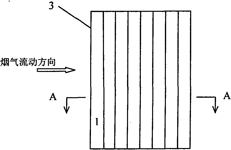
[0033] Stamping the electrostatic precipitator plate into figure 2 Strip panels shown, vertical strip 1 width W 1 , W 2 Both are 30mm, and the horizontal distance δ between adjacent vertical bars 1 is 1.0mm. Water is supplied to the dust-collecting plate 3 above the electrostatic precipitator, and the water film flowing downward is restricted within each vertical bar 1, forming a structure covering the entire vertical bar. 1, several water films form a water film covering the entire dust collecting plate 3.

Embodiment 2

[0035] Stamping the dust collector plate 3 into image 3 Strip panels shown, vertical strip 1 width W 1 , W 2 , W 3 Both are 20mm. The horizontal distance δ between adjacent vertical bars 1 is 0.5mm. Water is supplied to the dust collection pole plate 3 above the electrostatic precipitator, and the water film flowing downward is restricted in each vertical bar 1 to form a water film belt covering the entire vertical bar 1, and several water film belts are composed to cover the entire dust collection pole. Water film on plate 3.

Embodiment 3

[0037] Stamping the dust collector plate 3 into figure 2 Strip panels shown, vertical strip 1 width W 1 , W 2 They are 20mm and 40mm respectively, and the horizontal distance δ between adjacent vertical bars 1 is 0.6mm. Above the electrostatic precipitator, an atomizing nozzle is used to supply water to the dust collection plate 3, and the ash removal water is restricted to flow downward in each vertical bar 1, covering the entire vertical bar 1, and several vertical bars 1 form a water film to cover the entire dust collection plate 3 water film.


PUM


Abstract

The invention discloses a method for forming an ash removing water film for a wet electric dust remover and a dust collecting pole plate used by the same. The invention solves the problem that a water film for completely covering the pole plate can not be formed on a super-high pole plate higher than 10 meters, thus the wet electric dust remover can be used for removing dust in super-large-flow flue gas such as flue gas in coal burning boilers of thermal power plants and the like, and the invention has the advantages of reducing floor space, saving dust removing water, and the like. The method for forming the ash removing water film comprises the following steps: dividing the dust collecting pole plate into a plurality of vertical strip-shaped regions along the airflow direction, supplying water to the pole plate from the upper space of the dust collecting pole plate, limiting the dust removing water in each narrow strip-shaped region to flow downwards, and covering each small strip-shaped region, thereby forming the water film for completely covering the whole dust collecting pole plate.

Description

technical field [0001] The invention belongs to the field of flue gas purification for environmental protection, and in particular relates to a method for forming a dust-cleaning water film of a wet-type electric dust collector and a used dust-collecting pole plate. Background technique [0002] The wet electrostatic precipitator uses a layer of water film formed on the plate to clean the dust trapped on the plate. Water is supplied to the dust-collecting plate of the electrostatic precipitator above the dust collector, and the ash-cleaning water flows downward under the action of gravity to form a soot-cleaning water film covering the entire plate, taking away the dust collected on the dust-collecting plate, Fall into the ash hopper below the dust collector. Compared with the dry electrostatic precipitator, it has the following advantages: it does not need rapping equipment, thus eliminating the secondary dust caused by rapping, and can also prevent the secondary dust caus...

Claims


Application Information

Patent Timeline
Patent Type & Authority Applications(China)
IPC IPC(8): B03C3/16B03C3/47
Inventor 姜雨泽齐达立聂卫东林爱杰张永李乐丰江红
Owner ELECTRIC POWER RESEARCH INSTITUTE OF STATE GRID SHANDONG ELECTRIC POWER COMPANY
Why Eureka
Try Eureka