Exhaust hood for biomass energy converter

A technology of biomass energy and reformer, which is applied in the petroleum industry and the manufacture of combustible gas, etc. It can solve the problems of only vertical flow, easy blockage of carbon ash, and low efficiency of biomass energy reformer, so as to improve the gas production performance , to avoid the effect of dust clogging

Inactive Publication Date: 2010-08-04
詹汉忠
View PDF0 Cites 1 Cited by
  • Summary
  • Abstract
  • Description
  • Claims
  • Application Information

AI Technical Summary

Problems solved by technology

However, due to the unreasonable structure of the air diffuser device in the existing biomass energy conversion furnace, the air diffuser effect is poor.
During use: when the wind generated by the blower passes through the diffuser device, the wind direction can only flow vertically, so that the combustion materials in the combustion chamber of the biomass conversion furnace located on the upper floor can only be burned vertically along the wind direction, while the lower part and the upper layer surround The combustion materials are not completely burned, resulting in low efficiency of the biomass conversion furnace, and the open flame will not work after the materials are burned for 20-40 minutes
Moreover, the direction of the air guide hole of the traditional air diffuser is easy to be blocked by the carbon ash generated during the high temperature reaction process of the combustion material, which directly affects the work of the biomass conversion furnace

Method used


Image

  • Exhaust hood for biomass energy converter
  • Exhaust hood for biomass energy converter
  • Exhaust hood for biomass energy converter

Examples


Embodiment 1

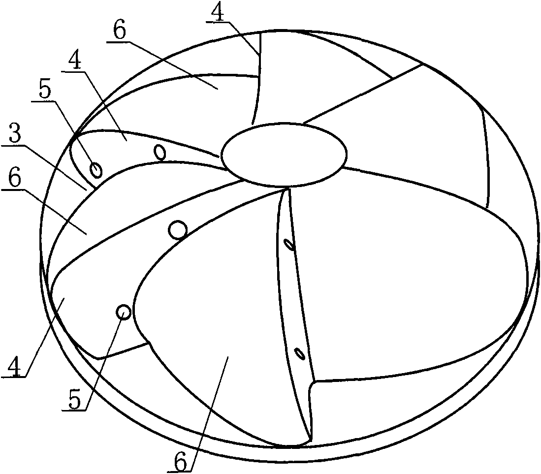
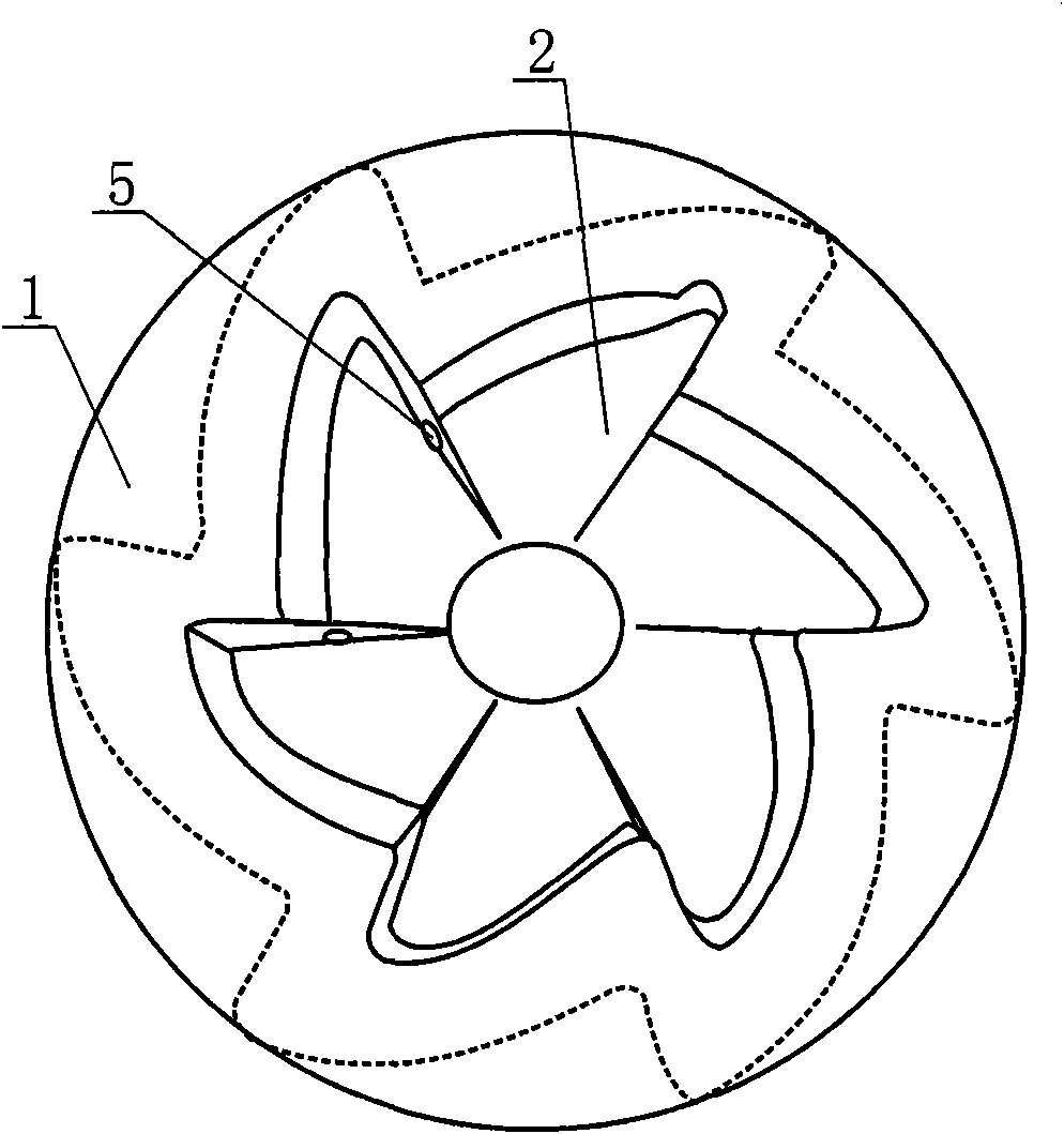
[0016] Embodiment 1: as figure 1 , figure 2 As shown, the fan hood for the biomass conversion furnace includes a cover body 1, and the inside of the cover body is a cavity 2, and a plurality of grooves 3 are distributed along the circumference on the outer surface of the cover body 1, forming a The impeller-shaped structure; the side wall 4 of the groove 3 is provided with a diffuser hole 5 , and the diffuser hole 5 communicates with the cavity 2 in the cover body 1 . One side wall 4 of the groove is perpendicular to the bottom surface, and the corresponding side wall 6 on the other side is an arc surface. The cover body is prefabricated from concrete.

Embodiment 2

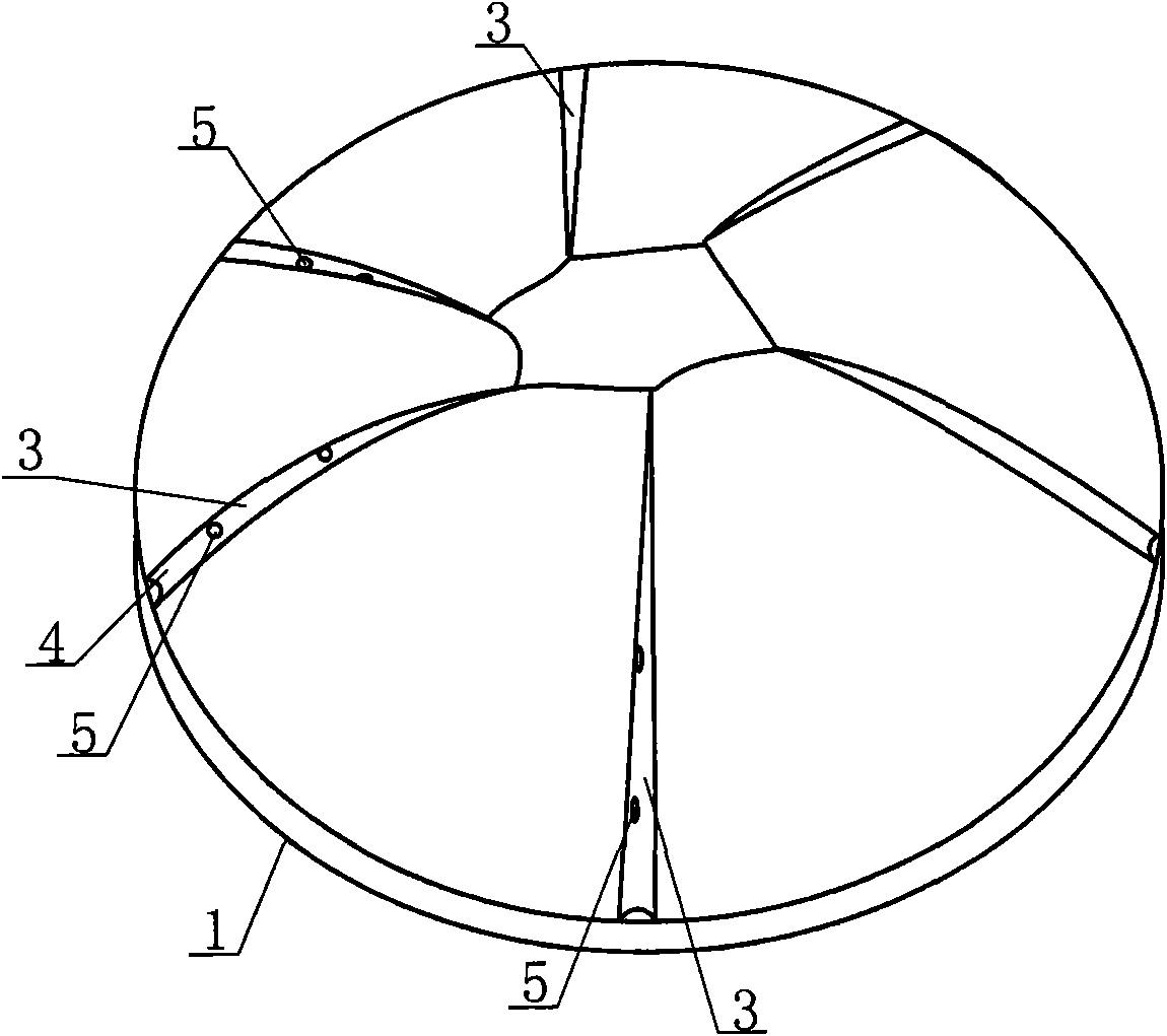
[0017] Embodiment 2: as image 3 As shown, the fan hood for the biomass conversion furnace includes a cover body 1, and the inside of the cover body is a cavity, and a plurality of grooves 3 are distributed along the circumference on the outer surface of the cover body 1; The side wall 4 of the groove 3 is provided with a diffuser hole 5 , and the diffuser hole 5 communicates with the cavity in the cover body 1 . The cover body is made of metal plate.

Embodiment 3

[0018] Embodiment 3: as Figure 4 As shown, the fan hood for the biomass conversion furnace includes a cover body 1, and the inside of the cover body is a cavity, and a plurality of grooves 3 are distributed along the circumference on the outer surface of the cover body 1; The side wall 4 of the groove 3 is provided with a diffuser hole 5 , and the diffuser hole 5 communicates with the cavity in the cover body 1 . The cover body is prefabricated from concrete. The outer surface of the cover body 1 is provided with two concentric air guiding inner rings 7 and air guiding outer rings 8 .


PUM


Abstract

The invention discloses an exhaust hood for a biomass energy converter. The exhaust hood for the biomass energy converter comprises a hood body (1) in which a cavity is formed, and is characterized in that: a plurality of grooves (3) are distributed at the periphery of an outer surface of the hood body (1); and exhaust holes (5) are reserved on side walls (4) of the grooves (3) and are communicated with the cavity in the hood body (1). The exhaust holes are reserved on the side walls of the grooves formed on the outer surface of the hood body, so wind enters a combustion chamber in a centrifugal radiation shape to form rotary wind, and a combustible material in the combustion chamber can be combusted sufficiently; the opening direction of the exhaust holes is changed to the horizontal direction from the conventional vertical direction, so the blockage due to dust is avoided; and through the structure, the gas generation performance is greatly improved.

Description

technical field [0001] The invention relates to a biomass energy conversion device for converting bio-organic fuel into combustible gas, in particular to a biomass energy conversion furnace ventilation hood. Background technique [0002] With the rapid development of my country's economy, the gap between the supply and demand of oil, natural gas, coal and other resources has increased year by year, and the price has also continued to rise. Many farmers are reluctant and cannot afford expensive gas and coal. Therefore, a kind of biomass energy conversion burner that improves the utilization rate of renewable energy appears on the market at present, so that the rural areas can use clean and cheap new energy. However, due to the unreasonable structure of the air diffuser device in the existing biomass energy conversion furnace, the air diffuser effect is poor. During use: when the wind generated by the blower passes through the diffuser device, the wind direction can only flow...

Claims


Application Information

Patent Timeline
Patent Type & Authority Applications(China)
IPC IPC(8): C10J3/72
Inventor 詹汉忠
Owner 詹汉忠
Why Eureka
Try Eureka