

Self-adaptive ship-intercepting method
An adaptive, ship-based technology, applied in the field of ship interception, can solve problems such as failure of anti-collision interception facilities, casualties, economic losses, etc., and achieve the effect of easy replacement and maintenance, flexible transition and use, and guaranteed interception effect
- Summary
- Abstract
- Description
- Claims
- Application Information
AI Technical Summary
Problems solved by technology
Method used
Image

Examples
Embodiment Construction
[0018] The present invention will be described in further detail below in conjunction with the accompanying drawings.
[0019] An adaptive ship interception method comprising the following steps:
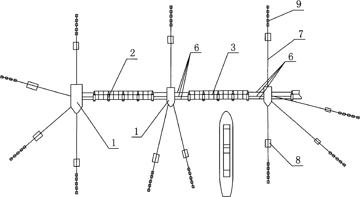
[0020] (1), place a plurality of mooring buoys 1 at a certain distance on the water surface, and connect anchor chains 7 that sink into the water in different directions of the mooring buoys 1, connect sinkers 8 on the anchor chains 7, and Connect the gravity anchor 9 at the end of the anchor chain 7;
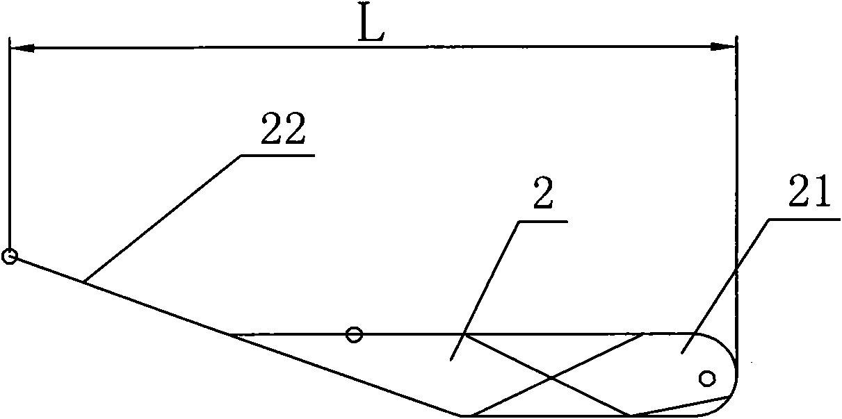
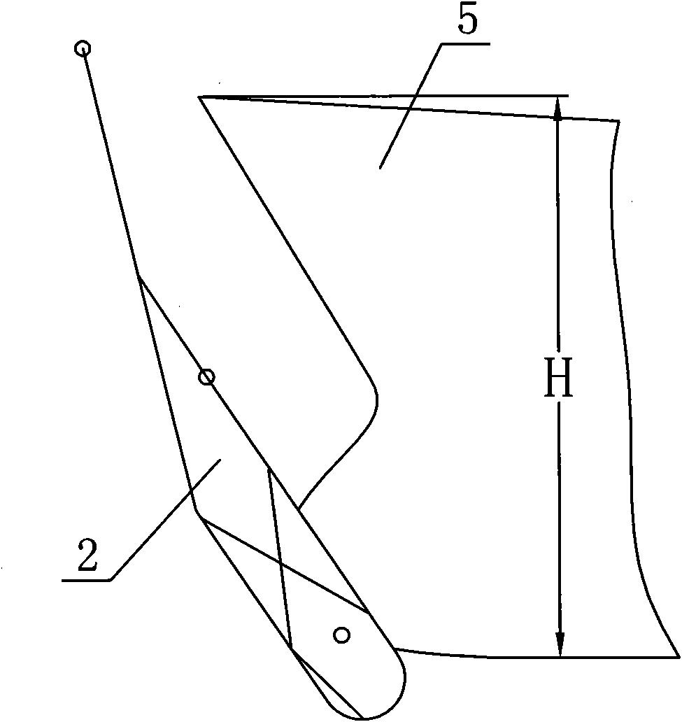
[0021] (2), select a plurality of buoys 2 with a length (L) greater than or equal to the height (H) of the bow 5, and the buoys 2 are tilted upward toward the end 22 of the bridge, and then these buoys 2 are floated on the water surface at certain intervals and horizontally Place it between the mooring buoys 1 in the above way, and make the center of buoyancy of the buoy 2 bias toward the end 21 of the buoy 2 facing the bow 5;
[0022] (3), the intercepting net 3 is horizontally de...
PUM
 Abstract
Description
Claims
Application Information