Pore plate grating system

An orifice plate and grid technology, which is applied in the field of sewage treatment, can solve the problems of reducing the interception accuracy, and achieve the effect of improving the removal rate, improving the effect of sewage treatment and compact structure.

Pending Publication Date: 2021-07-23
SCIMEE TECH & SCI CO LTD
View PDF10 Cites 0 Cited by
  • Summary
  • Abstract
  • Description
  • Claims
  • Application Information

AI Technical Summary

Problems solved by technology

[0005] The first aspect of the present invention is to solve the problem existing in the prior art that there is a large gap between the two ends of the orifice chain and the frame, which leads to serious water leakage and slag leakage and reduces the interception accuracy, and provides a The orifice grid system can effectively prevent sewage, especially grid slag, from leaking from the gap between the orifice chain and the frame, so that the sewage can only flow from one side of the orifice chain to the other side through the filter holes of the orifice, thus It can ensure the ability to intercept the grid slag, which is beneficial to improve the removal rate of the grid slag, and is more conducive to improving the sewage treatment effect; the main idea is:

Method used


Image

  • Pore plate grating system
  • Pore plate grating system
  • Pore plate grating system

Examples


Embodiment 1

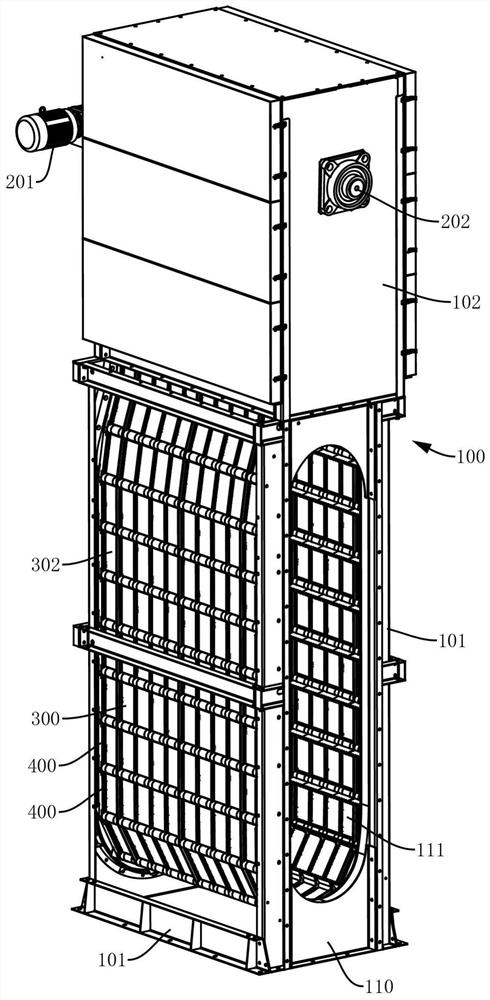
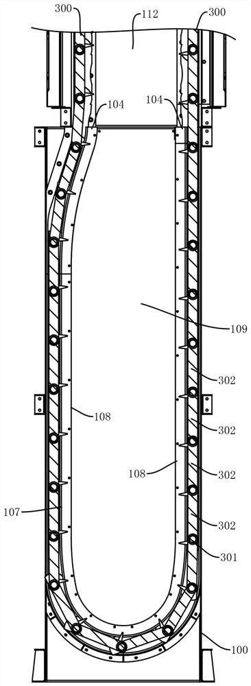
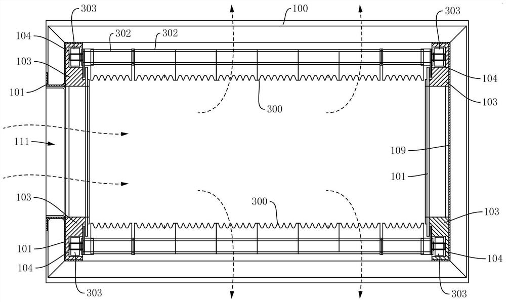
[0046] See Figure 1 - Figure 3 In this embodiment, a hole plate grid system includes a frame 100, a spindle 202 (or a chain axis), a hole plate chain 300, and power equipment 201, wherein

[0047] The rack 100 is mainly used to support support to mount and secure the remaining equipment, for example, in this embodiment, such as figure 1 and figure 2 As shown, the frame 100 includes a frame 101, and the frame 101 can be made of a conventional profile, for example, the frame 101 can preferentially adopt a rectangular structure in order to form an internal cavity 112 in the frame 101, such as figure 1 As shown, in actual operation, the lower portion of the frame 101 typically does not enter the water, and the upper portion of the frame 101 is typically located above the water surface to provide the main shaft 202, the power device 201, the flushing system, and the slag system, etc., the upper portion of the frame 101 Usually, a housing 102 is typically provided to enclose the interna...

Embodiment 2

[0070] The sealing problem between the sealing member 400 and the adjacent orifice plate 302, the main difference from the above-described Embodiment 1 is that in the orifice plate grid system provided in the present embodiment, the first sealing plate 401 or Side of the reinforcing strip 402 is constructed with parallel limiting convex 408, such as Figure 5 - Figure 10 As shown, the limiting projection 408 can preferentially employ a strip structure, and the two resilient projections 408 have a set distance for insertion of one side of the orifice plate 302. In the actual assembly, since the hole plate 302 is constrained between the adjacent two-way shaft 301, the sealing member 400 is just located on one side of the orifice plate 302 when the sealing member 400 is directly constrained by the adjacent two-way shaft 301. Figure 9 and Figure 10 As shown, at this time, the side of the orifice plate 302 can be inserted between the two limit projections 408, one aspect such that the s...


PUM


Abstract

The invention relates to a pore plate grating system which comprises a rack for supporting and two groups of guide grooves for guiding rotation of a pore plate chain, wherein the two groups of guide grooves are oppositely arranged; a main shaft which is rotatably mounted on the rack, wherein the main shaft is provided with a chain wheel; the pore plate chain which comprises a plurality of pore plates and a plurality of rotating shafts, the two ends of each pore plate are rotatably connected to the two adjacent rotating shafts respectively, the pore plates jointly define an annular structure, and the two ends of each rotating shaft are movably restrained in the guide grooves respectively; a plurality of sealing parts are arranged at the two ends of the pore plate chain respectively, each sealing part is provided with a first matching surface, at least one side of each guide groove is provided with a second matching surface, and the first matching surfaces and the second matching surfaces are mutually staggered and matched to form dynamic sealing; according to the pore plate grating system, the sealing parts are arranged so that sewage can flow out of the pore plate chain only through the filtering holes of the pore plate, the capability of intercepting grating slag can be ensured, and the sewage treatment effect can be improved.

Description

Technical field [0001] The present invention relates to the field of sewage treatment, and more particularly to a hole plate grid system. Background technique [0002] The well plate grille is very common in sewage treatment, usually with fine grills and ultra-fine grids, in practical applications, the orifice grid is separated from the size of different sizes of impurity garbage by the size of the filter hole, mainly The sewage is pretreated to provide convenience for subsequent processing; the intravation plate grid is one of the hole plate grid, which is a pretreatment device for the precision and efficient removal of hair and fine fibers in sewage in sewage treatment plants. It has strong interception capacity, high removal rate, wide application in the field of sewage treatment. [0003] The inner into the fluorescence plate grille typically includes a rack, a hole plate system (or a mesh system), a rinsing system (or a sprinkler system), a slag system, etc., wherein the o...

Claims


Application Information

Patent Timeline
Patent Type & Authority Applications(China)
IPC IPC(8): C02F1/00
CPCC02F1/00C02F2201/002
Inventor 毕永伟舒峰杨瑞连肖波王哲晓易洋蒋红光
Owner SCIMEE TECH & SCI CO LTD
Why Eureka
Try Eureka