Concrete gravity pillar type retaining wall

A technology for concrete piers and concrete, applied in the field of construction, can solve the problems of large impact on the surrounding environment, large working surface, vibration, high noise, etc., and achieve the effect of reducing the amount of engineering, balancing the stress of the base, and increasing the resistance moment.

Active Publication Date: 2012-04-25
CEEC JIANGSU ELECTRIC POWER DESIGN INST
View PDF6 Cites 0 Cited by
  • Summary
  • Abstract
  • Description
  • Claims
  • Application Information

AI Technical Summary

Problems solved by technology

In addition, the above various types of gravity retaining walls require a large working surface during construction, and the vibration and noise are large, which has a great impact on the surrounding environment.

Method used


Image

  • Concrete gravity pillar type retaining wall
  • Concrete gravity pillar type retaining wall
  • Concrete gravity pillar type retaining wall

Examples


Embodiment Construction

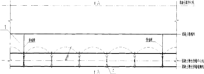
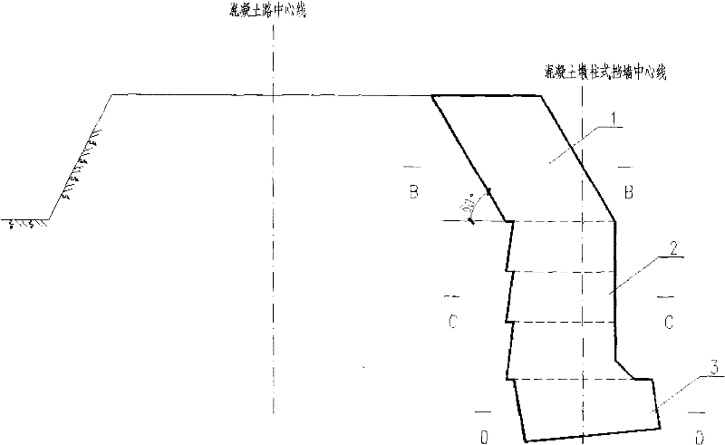
[0025] The concrete gravity pier type retaining wall of the present invention uses its own gravity to maintain the stability of the retaining wall under the action of water, earth pressure and vehicle load. The diameter of a single concrete pier is determined according to the bearing capacity of the foundation, the height of the retaining soil, the condition of the piled soil and the load of the vehicle. Generally, it is 1.6m-3.6m. The cross-section of the entire wall body is divided into three parts: the upper inclined parallelogram 1 (referred to as head-up), the middle chord-cut circle 2 (referred to as slimming), and the bottom gradual chord-cut circle 3 (referred to as heel cut). The upper elevation angle ranges from 80° to 45°, and the height accounts for about 1 / 3 of the total height of the entire wall. The different inclination angles of the inclined part determine the backward movement of the center of gravity of the entire wall, and the difference in height determines...


PUM


Abstract

The invention discloses a concrete gravity pillar type retaining wall. Each concrete gravity pillar is divided into three parts from the top to the bottom, comprising a rising section, a slim section and a heel cutting section. The wall is characterized in that the rising section is a parallelogram slanting backward, the slim section at the middle part is a flat-cut round concrete pillar with a vertical wall chest, the choosing range of the face-cut angle is from 90 DEG to 170 DEG, the heel cutting section at the lower part is a flat-cut round concrete pillar, and the flat-cut direction is opposite to that of the slim section. A plurality of separate concrete gravity pillar casts and forms a stress unit via the whole body of the rising section, and three parts of the wall structure of each stress unit supplements with each other to form an effective retaining structure. The invention fully develops the effect that the gravity center moves backwards and improves the self-stability, andcompared with the traditional gravity type retaining wall, the application range is enlarged, the work amount of the wall section is reduced, and the work cost is reduced.

Description

technical field [0001] The invention relates to a retaining structure widely used in municipal engineering and construction engineering, in particular to a gravity pier type retaining wall, which belongs to the technical field of construction. Background technique [0002] A gravity retaining wall is a structure that relies on its own weight to prevent soil slopes from collapsing. It relies on its own gravity to maintain the stability of the retaining wall under water and earth pressure. It can be built with bricks, stones, and concrete. Generally, it does not have steel bars or only a small amount of steel bars in a local area. It is a commonly used retaining wall at present. earthen wall. According to the different inclination directions of the wall back and the change of the line of the wall back, the section form of the wall body can be divided into several types such as upward slope, vertical, downward slope, convex broken line type and balance weight type. Comparing ...

Claims


Application Information

Patent Timeline
Patent Type & Authority Patents(China)
IPC IPC(8): E02D29/02
Inventor 王尉王磊姚刚沈锦儒杨明周元强
Owner CEEC JIANGSU ELECTRIC POWER DESIGN INST
Why Eureka
Try Eureka