Fuel distributor

A fuel dispenser and fuel distributing technology, applied in fuel injection devices, special fuel injection devices, charging systems, etc., can solve problems such as unoptimized, strong brazed joints, loads, etc., to achieve reasonable installation and reduced leakage Effect

Inactive Publication Date: 2010-08-04
BENTELER AUTOMOBILTECHNIK GMBH
View PDF5 Cites 8 Cited by
  • Summary
  • Abstract
  • Description
  • Claims
  • Application Information

AI Technical Summary

Problems solved by technology

A disadvantage here is that a non-optimized force flow reaches the distribution pipe via the position of the pressure introduction point in the injector receptacle, the fastening device receptacle and the soldered connection
The result is a strong load on the soldered connection

Method used


Image

  • Fuel distributor
  • Fuel distributor
  • Fuel distributor

Examples


Embodiment Construction

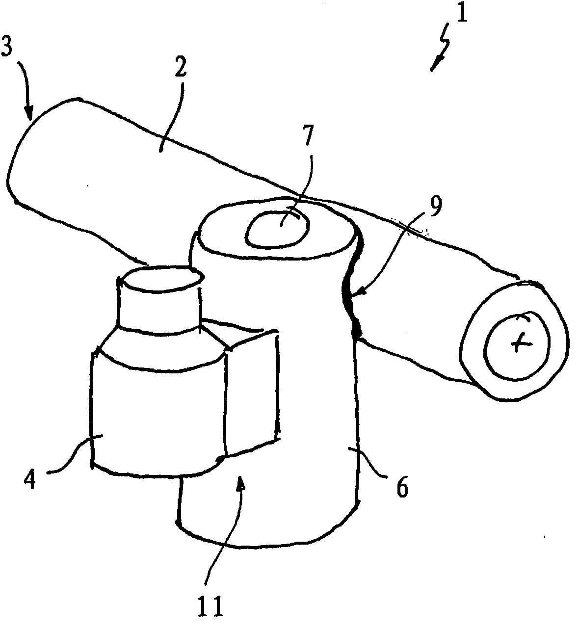
[0024] by means of Figures 1 to 3 The fuel distributor 1 according to the invention is explained. The fuel distributor 1 belongs to the storage injection system of the internal combustion engine. In such a store injection system, pressure generation and fuel injection are decoupled from each other. A separate high-pressure pump generates pressure continuously. The pressure that builds up independently of the injection sequence is provided permanently in the fuel distributor.

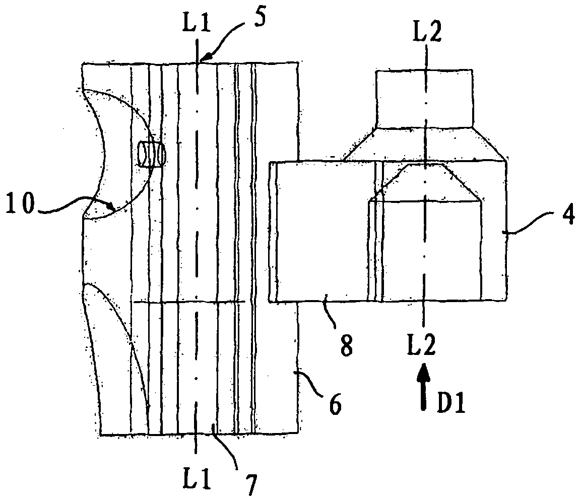
[0025] The fuel distributor 1 comprises a fuel inlet 3 with a pump side (in figure 1 Only schematically described in ) distribution pipe 2 and a plurality of injector receptacles 4 (only one of which is shown here). exist figure 2 Dispensing pipe 2 is not described in . The statically extruded fuel is stored in the distribution line 2 and distributed via the injector receptacle 4 to the injectors of the cylinder bank.

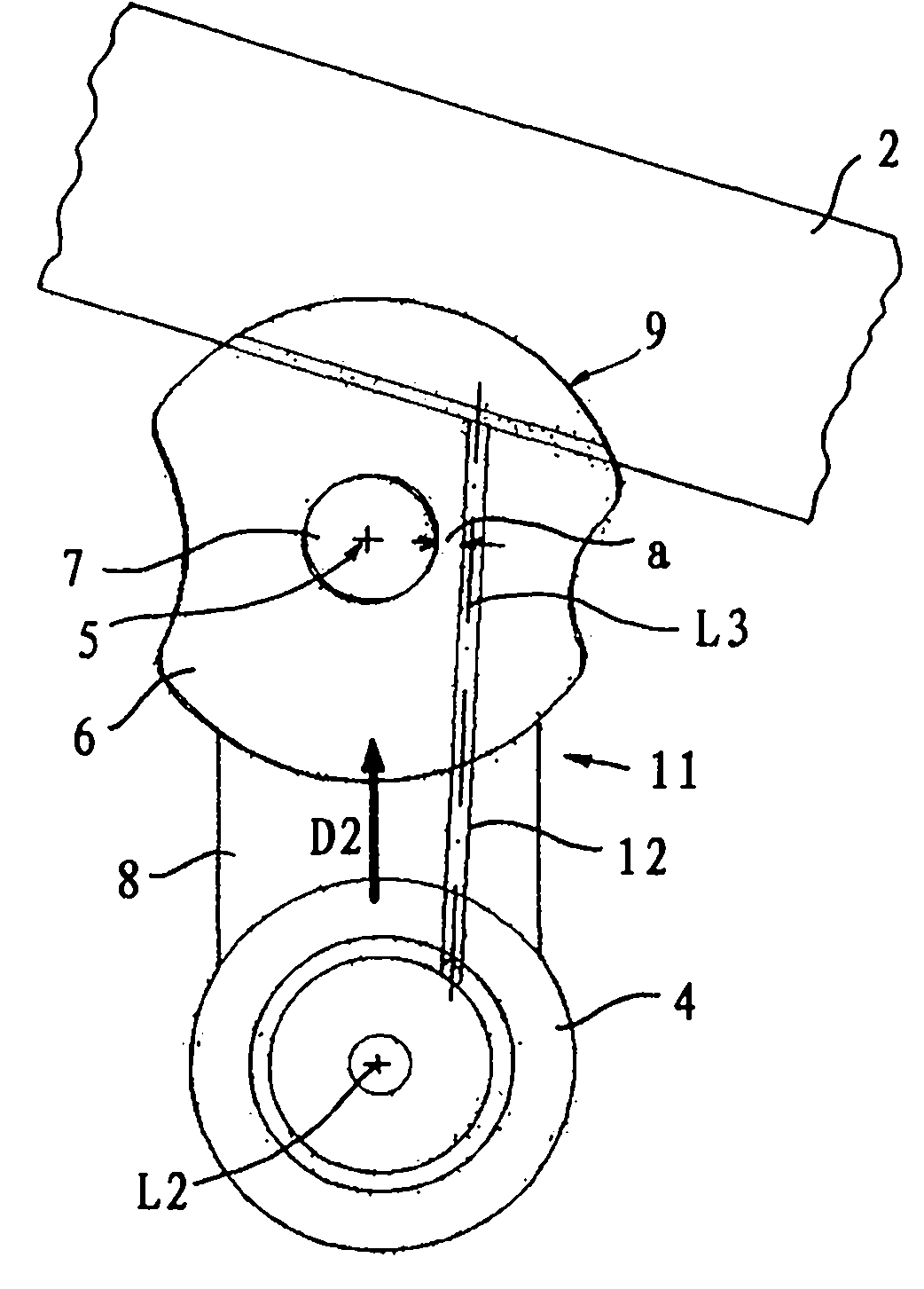
[0026] The distributor pipe 2 can be fastened to the internal combustion eng...


PUM


Abstract

A fuel distributor for conveying fuel to an injection valve of the internal combustion engine, is provided with a distributing pipe (2) for accommodating fuel at normal voltage and at least one injector accommodating part (4), wherein the distributing pipe has a fuel inlet (3), the injector accommodating part is connected to the distributing pipe through a connecting passage and the distributing pipe can be fixed on the internal combustion engine through at least one fixing element perforating the fixture unit accommodating part (6), the fixture unit accommodating part is connected to the distributing pipe through a brazing interconnecting piece (9) and the injector accommodating part is provided on the lateral surface (11) of the fixture unit accommodating part opposite to the brazing interconnecting piece, the connecting passage perforates the fixture unit accommodating part and the longitudinal axis of the connecting passage is transversal to the longitudinal axis of the perforation hole (7) perforating the fixture unit accommodating part.

Description

technical field [0001] The invention relates to a fuel distributor according to the features of the preamble of claim 1 for supplying fuel to injection valves of an internal combustion engine. Background technique [0002] Pressure generation and fuel injection are decoupled from each other in the fuel distribution system. The fuel pump builds pressure continuously. This pressure, which is generated independently of the injection sequence, is permanently available in the fuel distributor which serves as a store. The compressed fuel is thus stored in the distributor and distributed to the injectors or injection valves of the cylinder banks. [0003] Every fuel distributor, whether for high-pressure or low-pressure applications, must also be fastened to the internal combustion engine or its components, such as cylinders, cylinder heads or intake train modules. Usually this is done by means of screw connections. Mounting elements such as holders or the like are therefore us...

Claims


Application Information

Patent Timeline
Patent Type & Authority Applications(China)
IPC IPC(8): F02M55/02
CPCF02M2200/857F02M2200/855F02M55/025F02M61/168F02M2200/8084
Inventor D·茨维纳
Owner BENTELER AUTOMOBILTECHNIK GMBH
Why Eureka
Try Eureka