Helical water pump volute chamber structure of engine water pump

A screw type and engine technology, which is applied in the direction of machines/engines, liquid fuel engines, and components of pumping devices for elastic fluids, etc. It can solve the problems of increased power consumption of water pumps, increased fuel consumption of engines, and obvious water flow noise. Achieve the effect of reducing water flow resistance

Inactive Publication Date: 2010-08-04
CHONGQING CHANGAN AUTOMOBILE CO LTD
View PDF6 Cites 2 Cited by
  • Summary
  • Abstract
  • Description
  • Claims
  • Application Information

AI Technical Summary

Problems solved by technology

[0004] In the above structure, since the bottom surface of the vortex chamber is the same as the height of the mounting surface, after the water flow passes through the impeller 3, the circular arc diameter of the outer wall part of the vortex chamber water inlet channel 2 gradually becomes larger, so that the water inlet channel 2 gradually widens, reducing the width direction. flow resistance, but the water flow will still produce impact in the depth direction, and the water flow noise is more obvious
At the same time, the starting end of the water inlet channel 2 is not completely separated from the water outlet channel 1, and the high-pressure water flow in the water outlet channel 1 is easy to flow back into the water inlet channel 2. At the junction of the two, the water flow will form a backflow, generating a vortex area, which greatly reduces At the same time, the impact of water flow on the wall of the vortex chamber in the vortex area at the junction will generate relatively large water flow noise, which will increase the power consumption of the water pump, and eventually lead to increased fuel consumption of the engine and poor NVH performance

Method used


Image

  • Helical water pump volute chamber structure of engine water pump
  • Helical water pump volute chamber structure of engine water pump
  • Helical water pump volute chamber structure of engine water pump

Examples


Embodiment Construction

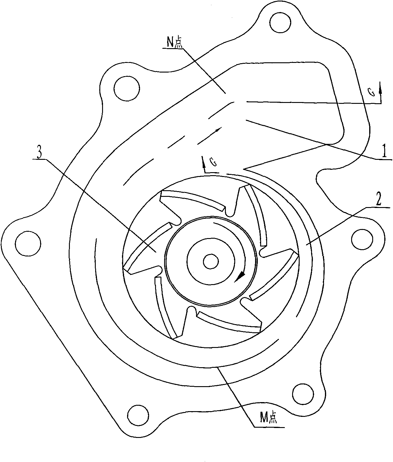
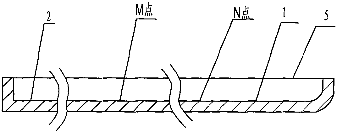
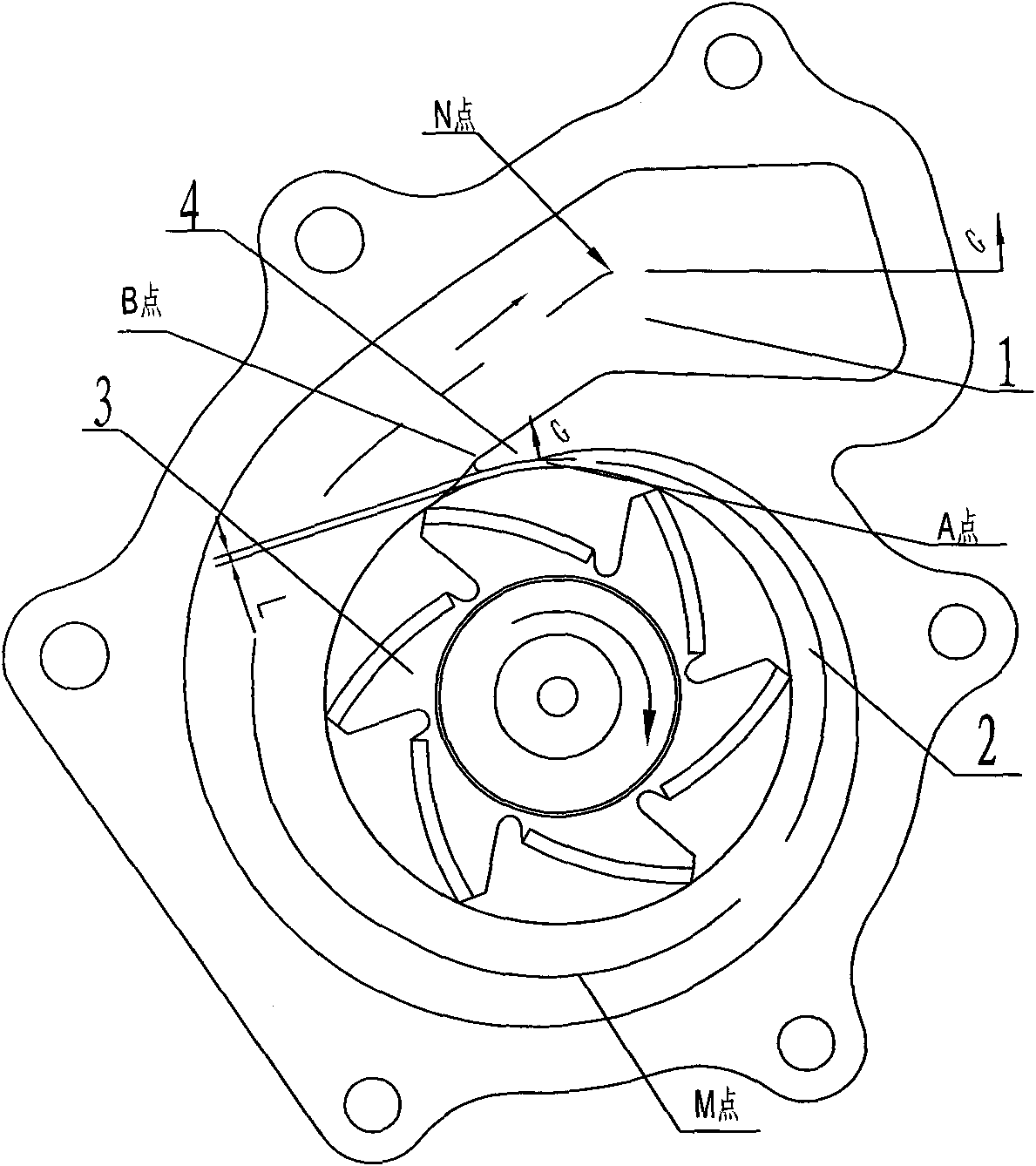
[0018] The structure of the vortex chamber of the spiral water pump is as follows: image 3 As shown: the vortex chamber is divided into three parts: the water outlet channel 1, the water inlet channel 2 and the tongue 4. The center of the vortex chamber is the area where the impeller 3 is installed. Between the contour line of the impeller rotation and the outer wall of the vortex, the impeller is surrounded to form a sequentially connected water inlet channel 2 and water outlet channel 1 in a spiral shape. The outer wall of the water inlet passage 2 of the vortex chamber is composed of 3 to 5 sections of arcs, and the diameter of the arcs gradually increases. At the same time, the dimension height from the bottom surface of the vortex chamber to the installation surface 5 of the pump body gradually deepens, such as Figure 4 Shown: Points M and N are respectively taken on the inlet and outlet channels of the vortex chamber. The cross-sectional heights of the two points are ...


PUM


Abstract

The invention discloses a helical water pump volute chamber structure of an engine water pump, wherein a center of the volute chamber part is an area where an impeller are installed, the impeller is surrounded between a rotary contour line of the impeller and the outer wall of the volute chamber to form a helical water intake channel and a helical water drainage channel connected in sequence, the width of the water intake channel increases gradually and the channel from the water intake channel to the water drainage channel deepens gradually, a separation tongue is designed at the junction of the start point A of the water intake channel and the start point B of the water drainage channel to separate two channels. The structure can thoroughly solve the liquid backflow problem at the junction of inlet and outlet without forming vortex area, and simultaneously reduce resistance of water streams in all directions to promote the efficiency of water pump and lower the noise of water stream.

Description

technical field [0001] The invention relates to an engine cooling system, in particular to a vortex chamber structure of an engine water pump assembly. Background technique [0002] The performance design of the engine water pump assembly not only affects the performance of the cooling system, but also affects the overall energy consumption and NVH of the engine. The impact on the performance of the pump mainly includes the structure of the impeller and the vortex chamber of the pump. [0003] Generally, the structure of the vortex chamber of the engine water pump is as follows: figure 1 As shown: the vortex chamber is set on the pump body of the water pump, including two parts: the water outlet channel 1 and the water inlet channel 2. The water inlet channel 2 surrounds the impeller 3, and its outer wall part is composed of 3 to 5 arcs, and the dimension and height from the bottom surface of the vortex chamber to the installation surface 5 are the same, such as figure 2...

Claims


Application Information

Patent Timeline
Patent Type & Authority Applications(China)
IPC IPC(8): F04D29/42F04D29/58
Inventor 袁浩尹强何朝春刘智军梁文锋
Owner CHONGQING CHANGAN AUTOMOBILE CO LTD
Why Eureka
Try Eureka