High-precision time-delay precompensation optical fiber timing method

A pre-compensation and delay technology, applied in optical fiber transmission, time division multiplexing system, electromagnetic wave transmission system, etc., can solve the problems of poor stability, high cost, complex system, etc., and achieve high stability and accuracy. , the effect of the unification of benchmarks

Inactive Publication Date: 2010-08-04
PLA UNIV OF SCI & TECH
View PDF1 Cites 34 Cited by
  • Summary
  • Abstract
  • Description
  • Claims
  • Application Information

AI Technical Summary

Problems solved by technology

[0009] The purpose of the present invention is to propose a high-precision time-delay pre-compensation optical fiber timing method for the problems of high cost, poor stability and complex system in which the time delay compensation is completed at the terminal station to realize second pulse recovery in the existing timing methods

Method used


Image

  • High-precision time-delay precompensation optical fiber timing method
  • High-precision time-delay precompensation optical fiber timing method
  • High-precision time-delay precompensation optical fiber timing method

Examples


Embodiment Construction

[0030] The present invention will be further described below in conjunction with the accompanying drawings and embodiments.

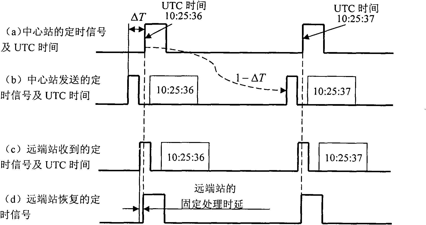
[0031]The end station that sends the second pulse is called the timing central station, referred to as the central station; the end station that receives the second pulse is called the timing terminal station, referred to as the terminal station.

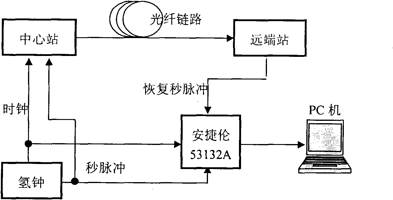
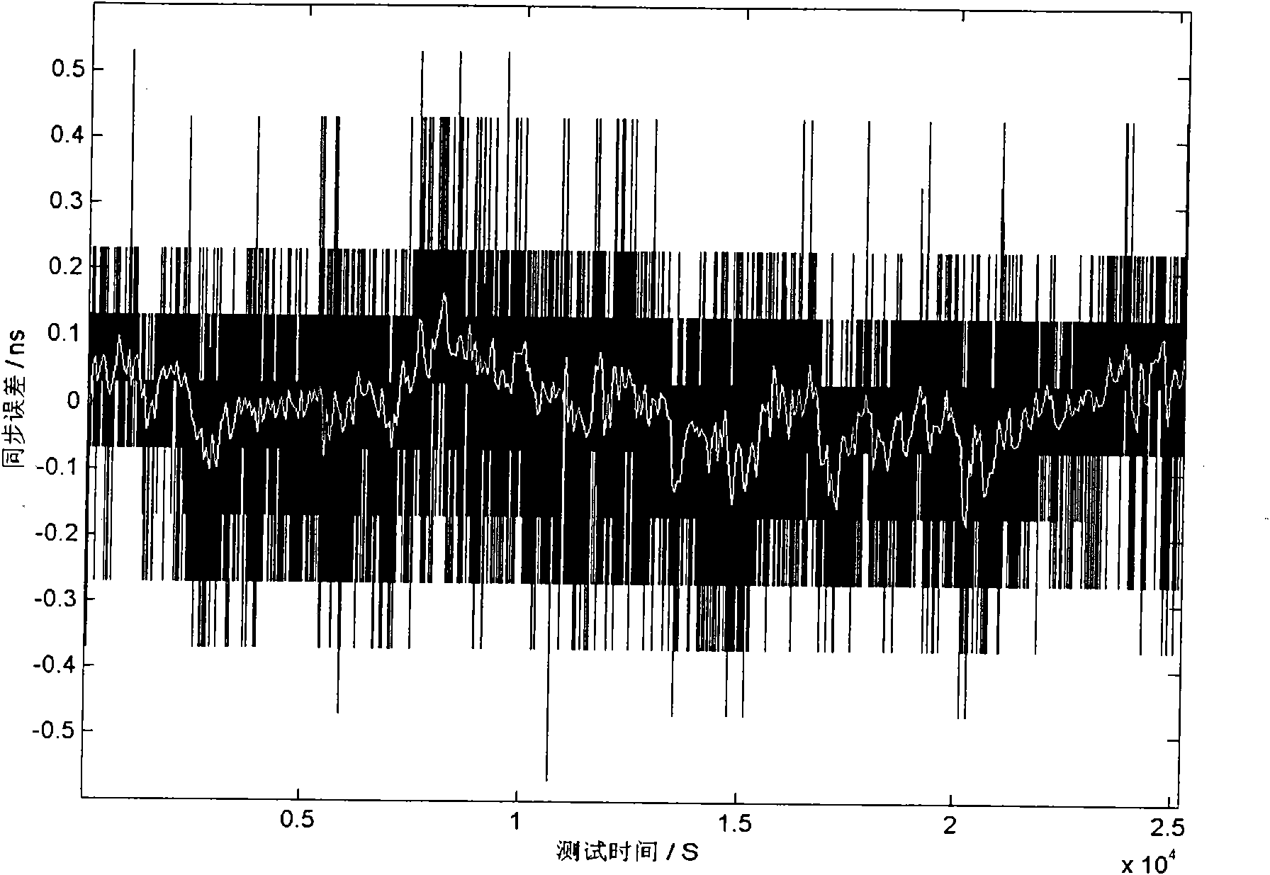
[0032] Agilent 53132A: A frequency counter that measures frequency, time interval, phase, and counts against time. In the present invention, an Agilent measuring instrument is used to detect the accuracy and stability of time transfer.

[0033] Such as figure 1 As shown, the high-precision delay precompensation optical fiber timing method of the present invention comprises the following steps:

[0034] (a). The central station system is powered on, and the second pulse is sent after encoding.

[0035] (b). The terminal station extracts the second pulse signal output from the received line code stream, and ...


PUM


Abstract

The invention relates to a high-precision time-delay precompensation optical fiber timing method which comprises the following steps of: firstly, extracting a PPS (Pulse Per Second) signal from a received line code stream and outputting by a terminal station; circularly returning the received line code stream to a center station; recovering the PPS signal from the circularly returned line code stream by the center station; measuring a time interval between a sending PPS and a recovered PPS; subtracting a bidirectional time delay of terminal equipment to acquire an optical fiber link bidirectional transmission time delay; calculating a one-way time delay from the center station to the terminal station; and adding a one-way time delay value of the terminal equipment to acquire a precompensation time delay. The precompensation value is used as a precompensation time delay of the next PPS and coded before the next PPS is sent to the terminal station. The invention has the advantages of uniform reference and high stability and is easy to simultaneously ensure the long-term stability and the short-term stability of time transmission.

Description

technical field [0001] The present invention relates to a method of time transfer, especially a method for realizing precise time synchronization signal (also known as second pulse) transfer by using a single optical fiber link, that is, a method for realizing precise time service in different places, specifically a high-precision time delay pre-compensation Optical fiber timing method. Background technique [0002] All major countries in the world are actively developing their own high-performance time and frequency systems. The most famous ones are space-based timing systems, such as the GPS system in the United States, the GLONASS in Russia, the Galileo system in Europe, and the Beidou system under construction in my country. At present, the timing services that my country can provide to ordinary people and special users include short-wave timing (BPM), long-wave timing (BPL), satellite timing, Internet timing, and TV timing services. Space-based time-frequency networks ...

Claims


Application Information

Patent Timeline
Patent Type & Authority Applications(China)
IPC IPC(8): H04J3/06H04B10/12H04B10/25
Inventor 吴传信卢麟丁晓玉朱勇王荣陈亦望
Owner PLA UNIV OF SCI & TECH
Why Eureka
Try Eureka