
Wheel-pendulum compound driving device for small mobile robot

A mobile robot and driving device technology, applied in the field of robotics and automation, can solve the problems of increasing the complexity and cost of the mechanism, complicated mechanism and control, and large frictional resistance, saving turning space, simple and reliable control, and obstacle-surmounting ability. strong effect

Inactive Publication Date: 2011-11-30
ZHEJIANG UNIV
View PDF1 Cites 0 Cited by
  • Summary
  • Abstract
  • Description
  • Claims
  • Application Information

AI Technical Summary

Problems solved by technology

[0002] At present, in the motion mechanism of mobile robots, wheeled, crawler and footed mechanisms are generally used. Wheeled mobile robots have the characteristics of simple structure, fast moving speed and easy manipulation, but they are not suitable for crossing obstacles such as steps and ravines; Tracked robots have high traversing ability and good environmental adaptability in natural environments such as soft and uneven terrain, but have high frictional resistance and high energy consumption; legged mobile robots have high mobility and are easy to adapt A variety of complex ground environments, but the mechanism and control are complex and expensive
In recent years, many scholars have carried out research on mobile robots based on composite mechanisms, but many of them only combine wheeled, legged or tracked, legged mechanisms together. Yao Yanan, Shi Kan and others from Beijing Jiaotong University applied in 2007 Patent (publication number: CN 101157372A) of a walking-wheel-track composite mobile robot, although the wheel-type, crawler-type and leg-type mechanisms are combined together, a telescopic rod mechanism is used in the middle and the force is carried out by rack and pinion or hydraulic pressure. The transfer of the system greatly increases the complexity and cost of the organization, and makes the control more complicated

Method used


Image

  • Wheel-pendulum compound driving device for small mobile robot
  • Wheel-pendulum compound driving device for small mobile robot
  • Wheel-pendulum compound driving device for small mobile robot

Examples


Embodiment Construction

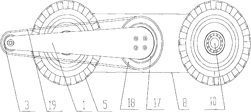
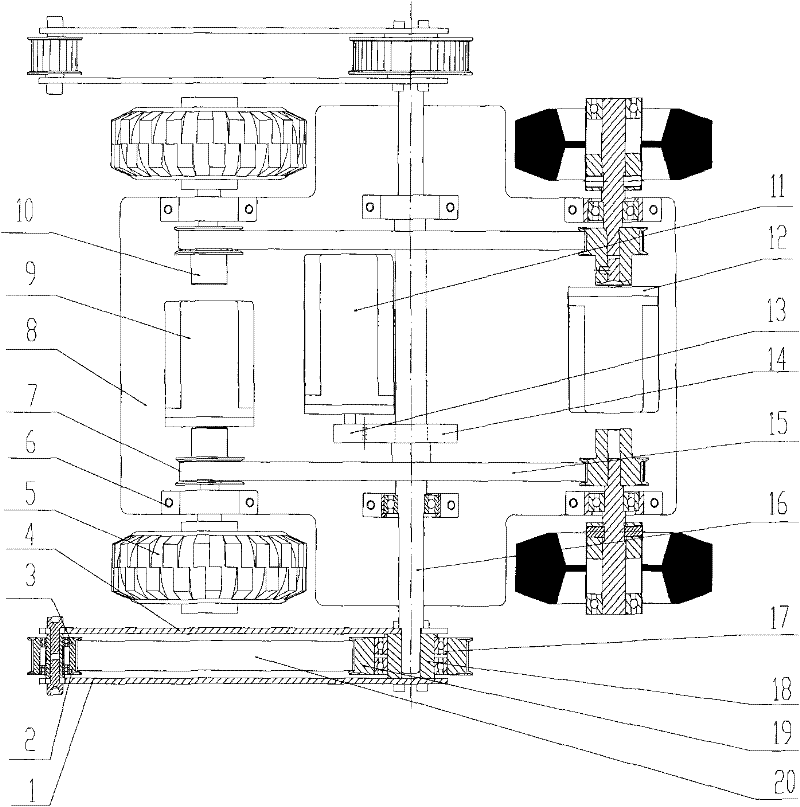
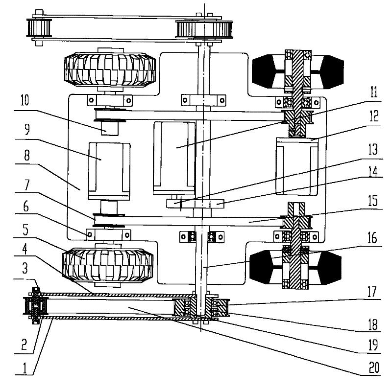
[0013] The present invention includes two outer connecting plates, two inner connecting plates, four small swing arm bearings, four large swing arm bearings, two small pulleys, two large pulleys, four wheels, six bearing seats, Four drive pulleys, base plate, two drive motors, four drive shafts, swing arm motor, three motor mounts, pinion gear, bull gear, main shaft, two bushings, two timing belts and two swing arm belts ; Two drive motors are diagonally fixed at both ends of the base plate through two motor seats, the output shaft of the drive motor is connected with one end of the drive pulley through a set screw, and the other end of the drive pulley is connected with one end of the drive shaft through a tightening Screw connection, the other end of the drive shaft is connected with the pulley, the middle of the drive shaft is fixed on the bottom plate through the bearing seat, and the drive pulley is connected with the drive pulley on the same side through the timing belt, ...


PUM


Abstract

The invention discloses a wheel-pendulum compound driving device for a small mobile robot. Two motors are diagonally fixed at both ends of the bottom plate, and the wheels are driven by synchronous belt pulleys, wherein the two pulleys on the same side pass through the motors installed on the same side For driving, the two pulleys are connected through a synchronous belt, so that the trolley can realize four-wheel drive and the turning direction of the trolley can be realized by controlling the rotation direction of the two motors, so as to save the turning radius and movement space; the middle part of the trolley is equipped with a swing arm , the swing arm includes inner and outer connecting plates, bearings, synchronous belts and synchronous pulleys, which are driven by a motor installed in the middle of the trolley through gear transmission, and can play the role of auxiliary legs and crawlers when passing through larger obstacles. Improve its ability to overcome obstacles.

Description

technical field [0001] The invention belongs to the field of robot technology and automation, in particular to a wheel-pendulum compound driving device for a small mobile robot. Background technique [0002] At present, in the motion mechanism of mobile robots, wheeled, crawler and footed mechanisms are generally used. Wheeled mobile robots have the characteristics of simple structure, fast moving speed and easy manipulation, but they are not suitable for crossing obstacles such as steps and ravines; Tracked robots have high traversing ability and good environmental adaptability in natural environments such as soft and uneven terrain, but have high frictional resistance and high energy consumption; legged mobile robots have high mobility and are easy to adapt All kinds of complex ground environments, but the mechanism and control are more complicated and expensive. In recent years, many scholars have carried out research on mobile robots based on composite mechanisms, but m...

Claims


Application Information

Patent Timeline
Patent Type & Authority Patents(China)
IPC IPC(8): B62D57/02
Inventor 陈文华李星军刁常堃刘娟李立新
Owner ZHEJIANG UNIV
Learn More