
Composite box girder bridge erected in advance by using corrugated steel web steel girders and construction method thereof

A technology of steel webs and combined boxes, applied in the field of combined box girder bridges and their construction, can solve the problems that the self-weight internal force accounts for a large proportion of the designed internal force, affects the durability of the bridge's load-bearing performance, and the tensile strength is insufficient, so as to improve the construction quality , good social and economic effects, and the effect of improving live load efficiency

Active Publication Date: 2010-08-11
GUANGDONG PROVINCE COMM PLANNING & DESIGN INST
View PDF9 Cites 19 Cited by
  • Summary
  • Abstract
  • Description
  • Claims
  • Application Information

AI Technical Summary

Problems solved by technology

[0002] At present, the web of an ordinary concrete box girder is integrated with the top and bottom slabs, and the stress problems caused by the temperature difference between the top and bottom slabs and the drying and constriction of the web are relatively prominent. Insufficient shear and tensile strength will lead to various cracks, which seriously affect the load-bearing performance and durability of the bridge
The traditional folded steel web combined box girder can solve the above problems well, but because the design and structure of small and medium-sized bridges usually adopt full-height brackets, it will seriously affect the traffic under the bridge or it is difficult to realize when the pier is high.

Method used


Image

  • Composite box girder bridge erected in advance by using corrugated steel web steel girders and construction method thereof
  • Composite box girder bridge erected in advance by using corrugated steel web steel girders and construction method thereof
  • Composite box girder bridge erected in advance by using corrugated steel web steel girders and construction method thereof

Examples


Embodiment Construction

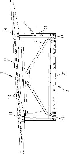
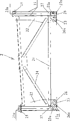
[0034] Such as Figure 1 to Figure 6 The shown one uses folded steel web steel girders to erect a composite box girder bridge in advance, including a concrete floor 3, a steel beam 2 and a concrete roof 1, the steel beam 2 is connected to the concrete floor 3 and the concrete roof 1 respectively, and the concrete floor 3 Installed on the steel beam 2, and bearing the concrete roof 1, the steel beam 2 is a folded steel web steel beam structure, and each steel beam 2 includes a pair of folded steel webs 21 vertically symmetrically arranged and erected on a pair of folded steel webs. The hollow-type diaphragm unit between the steel webs, the upper end of the folded steel web 21 is provided with an upper connection mechanism for fastening with the concrete roof 1, and the lower end of the folded steel web 21 is provided with an upper connection mechanism for connecting with the concrete bottom plate 3 Tighten the connected lower link mechanism.

[0035] The fasting diaphragm unit...


PUM


Abstract

The invention discloses a composite box girder bridge erected in advance by using corrugated steel web steel girders. The bridge comprises a concrete soleplate, a steel girder and a concrete upper top plate, wherein the steel girder is a corrugated steel web steel girder structure; the steel girder comprises a pair of corrugated steel webs which is arranged vertically and symmetrically and an open-web diaphragm unit erected between the pair of corrugated steel webs; and the upper end of each corrugated steel web is provided with an upper connecting mechanism to be firmly connected with the concrete top plate, and the lower end of the corrugated steel web is provided with a lower connecting mechanism to be firmly connected with the concrete soleplate. The invention also discloses a construction method for the composite box girder bridge erected in advance by using the corrugated steel web steel girders. The corrugated steel webs are used as composite box girder webs, so dead weight of a structure is reduced, live load efficiency is enhanced and a cracking problem of a conventional concrete box girder web is solved; and simultaneously, bracket-free construction can be realized in a high pier, construction quality is enhanced, construction process is fastened and remarkable economic and social benefits are achieved.

Description

technical field [0001] The invention relates to a composite box girder bridge and a construction method thereof, in particular to a composite box girder bridge erected in advance by using folded steel web steel girders and a construction method thereof. Background technique [0002] At present, the web of an ordinary concrete box girder is integrated with the top and bottom slabs, and the stress problems caused by the temperature difference between the top and bottom slabs and the drying and constriction of the web are relatively prominent. Insufficient shear resistance and tensile strength lead to various cracks, which seriously affect the load-bearing performance and durability of the bridge. The traditional box girder with folded steel webs can better solve the above problems, but because the design and structure of small and medium bridges usually use full-height supports, the construction seriously affects the traffic under the bridge or it is difficult to realize when ...

Claims


Application Information

Patent Timeline
Patent Type & Authority Applications(China)
IPC IPC(8): E01D2/04E01D21/00E04C3/293
Inventor 梁立农卢绍鸿刘玉擎孙颖梁雄王倩刘桂红
Owner GUANGDONG PROVINCE COMM PLANNING & DESIGN INST
Learn More