
Fault prediction method and device thereof for rotation equipment

A technology for rotating equipment and fault prediction. It is used in measuring devices, measuring ultrasonic/sonic/infrasonic waves, instruments, etc. It can solve the problems of heavy load, harsh working conditions, and narrow practical range, and achieve high judgment success rate and high judgment value. , the effect of high computing speed

Inactive Publication Date: 2011-05-25
BEIJING INFORMATION SCI & TECH UNIV
View PDF0 Cites 1 Cited by
  • Summary
  • Abstract
  • Description
  • Claims
  • Application Information

AI Technical Summary

Problems solved by technology

However, for a large number of mechanical equipment used in industrial sites, many of the key equipment have high power, heavy and unstable loads, and harsh working conditions. Measures need to be taken to ensure the normal operation of the mechanical equipment and scientific maintenance
Which failure prediction method is the most effective and economical for different mechanical equipment, the existing test prediction technology is often unable to determine and measure
The use of a prediction model can only effectively realize the state trend prediction for a certain type of equipment under specific working conditions. The practical scope is narrow, and it cannot be popularized and applied to equipment under different working conditions.

Method used


Image

  • Fault prediction method and device thereof for rotation equipment
  • Fault prediction method and device thereof for rotation equipment
  • Fault prediction method and device thereof for rotation equipment

Examples


Embodiment Construction

[0013] The present invention will be described in detail below in conjunction with the accompanying drawings and embodiments.

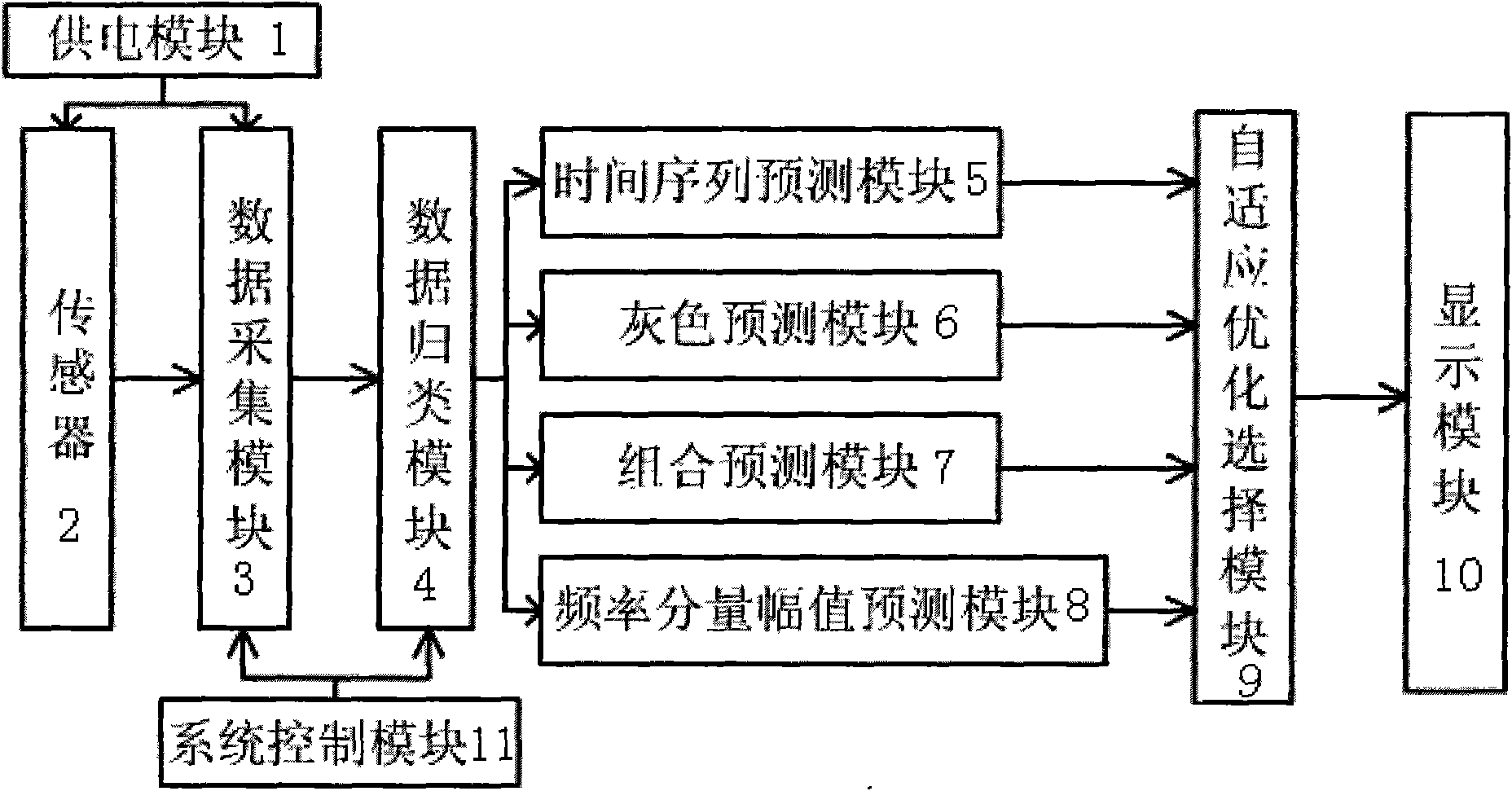
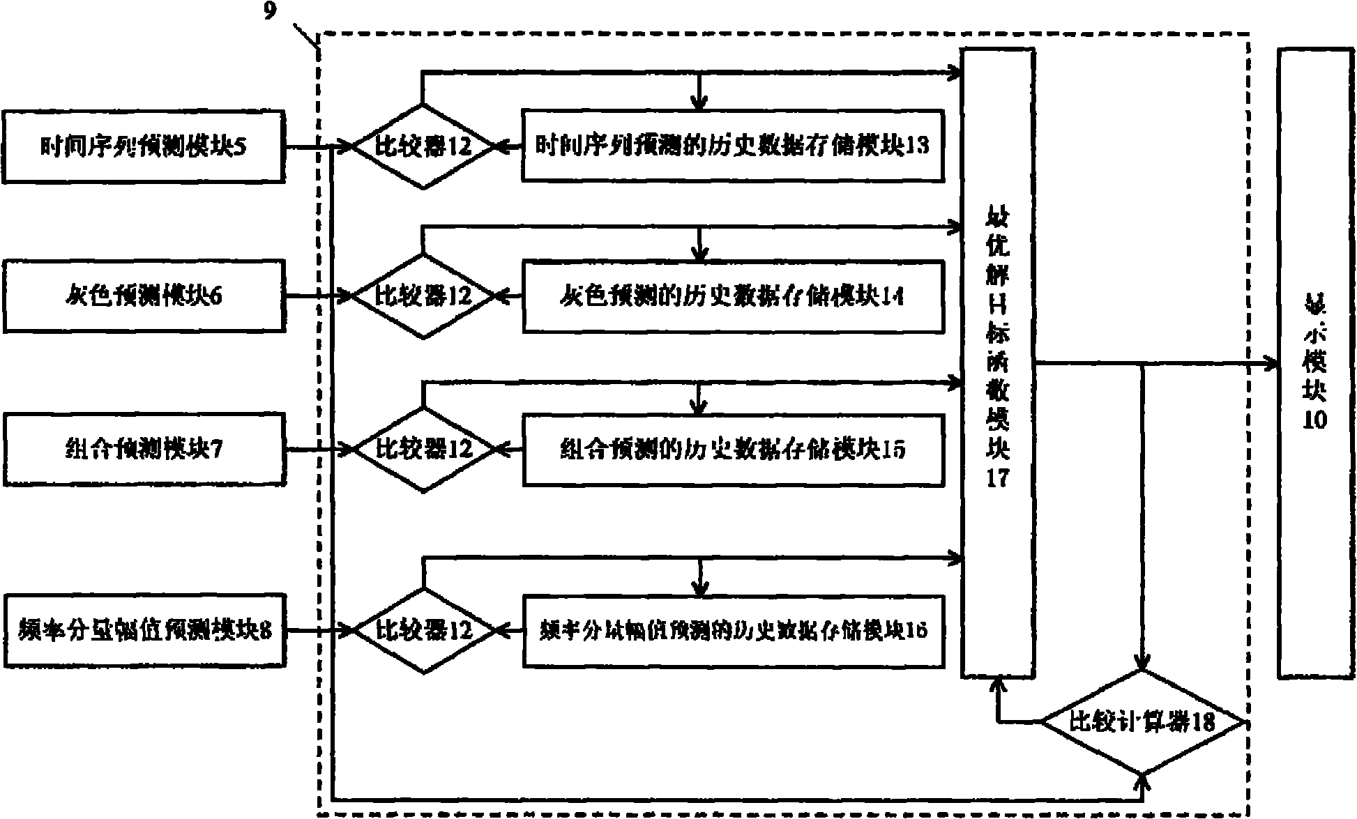
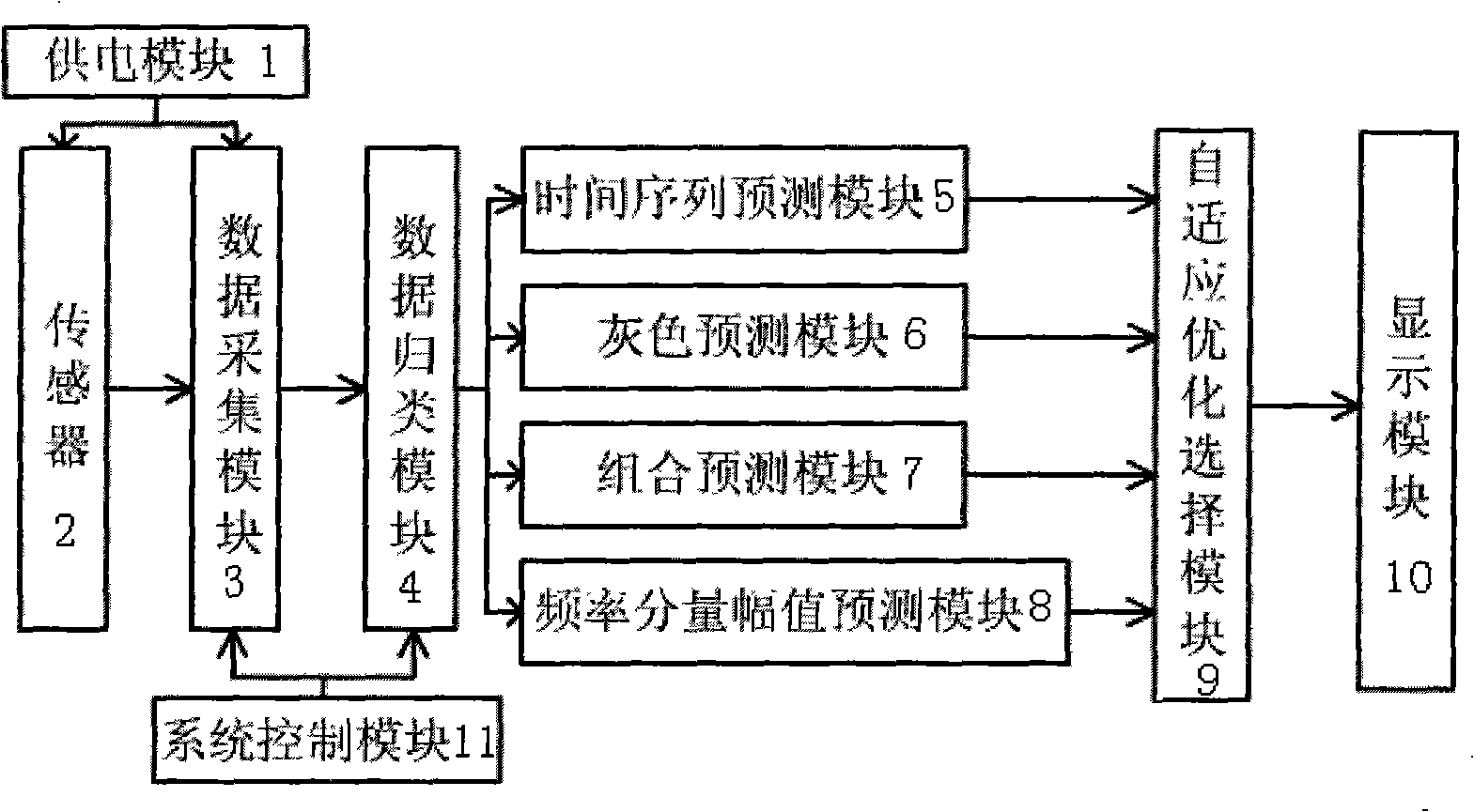
[0014] Such as figure 1 As shown, the present invention includes a power supply module 1, a sensor 2, a data acquisition module 3, a data classification module 4, a time series prediction module 5, a gray prediction module 6, a combined prediction module 7, a frequency component Amplitude prediction module 8, an adaptive optimization selection module 9, a display module 10 and a system control module 11; the output terminals of the power supply module 1 are respectively connected with the sensor 2 and the data acquisition module 3 to realize its power supply function. The sensor 2 sends the detected vibration signal into the data acquisition module 3, and then the data acquisition module 3 sends the vibration signal into the data classification module 4 for classification processing, and then sends it to the time series prediction module 5 and the gra...


PUM


Abstract

The invention relates to a fault prediction method and a device thereof for rotation equipment. The method comprises the following steps (1) setting a testing device comprising a power supply module, a sensor, a data collection module, a data sorting module, a time sequence predicting module, a gray prediction module, a combined prediction module, a frequency component amplitude value prediction module, a self-adaptive optimization selection module, a display module and a system control module; (2) collecting vibration signals suitable for four prediction modules by the data collection moduleto be used as historical data; (3) using the data collection module for collecting the vibration signals under various conditions in real time to be used as current data; (4) using a trend predication method for analyzing the stored data; (5) after analyzing and processing vibration signals collected in a next moment, comparing the vibration signals to results obtained by the trend predication method; and (6) obtaining an optimum prediction model after the comparison. The invention adopts the fault prediction device in a modularized structure, can adapt to the requirements of different rotation equipment, and can realize the real-time on-line prediction on the state of the rotation equipment. The invention can be widely applied to the fault prediction detection analysis of various kinds of rotation equipment.

Description

technical field [0001] The invention relates to a method and device for predicting mechanical failure, in particular to a method and device for predicting failure of rotating equipment in the field of on-line state detection of rotating equipment. Background technique [0002] People have always paid great attention to the condition monitoring and fault detection of rotating equipment. Ensuring the safe and reliable operation of equipment can not only improve production efficiency but also reduce equipment maintenance costs. For large and medium-sized mechanical equipment, the traditional maintenance method is "time-based preventive maintenance", also known as regular maintenance. The main feature of this maintenance method is that it is regularly inspected and repaired according to the artificially planned time regardless of whether the equipment is faulty or not. In order to avoid huge economic losses caused by unexpected shutdown of important mechanical equipment, the ti...

Claims


Application Information

Patent Timeline
Patent Type & Authority Patents(China)
IPC IPC(8): G01H17/00
Inventor 徐小力吴国新王红军谷玉海
Owner BEIJING INFORMATION SCI & TECH UNIV
Learn More