Fluoroscopy

A technology of perspective photography and X-ray, which is applied in the fields of diaphragm for radiation diagnosis, equipment for radiation diagnosis, medical science, etc. It can solve problems such as image blur and distortion, and achieve the effect of reducing burden and solving blur and distortion

Active Publication Date: 2010-08-11
SHIMADZU CORP
View PDF1 Cites 8 Cited by
  • Summary
  • Abstract
  • Description
  • Claims
  • Application Information

AI Technical Summary

Problems solved by technology

[0011] The object of the present invention is to solve the problems of excessive exposure to the subject 7 and blurring and distortion of images caused by oblique photography when pe

Method used


Image

  • Fluoroscopy
  • Fluoroscopy
  • Fluoroscopy

Examples


Example Embodiment

[0051] Example 1

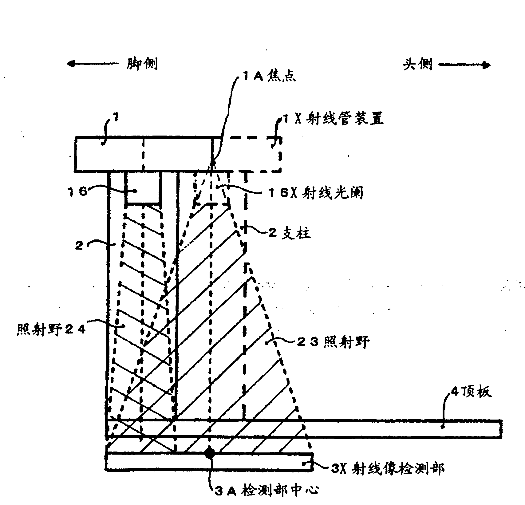
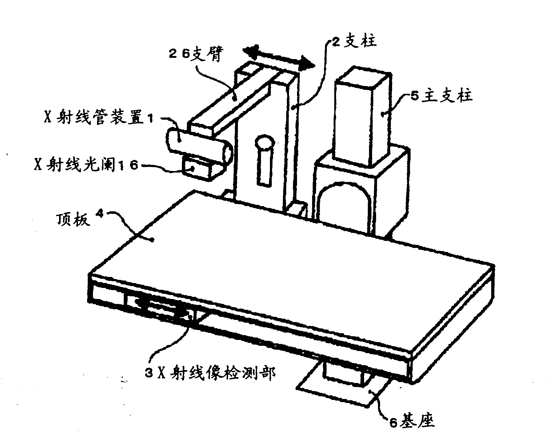
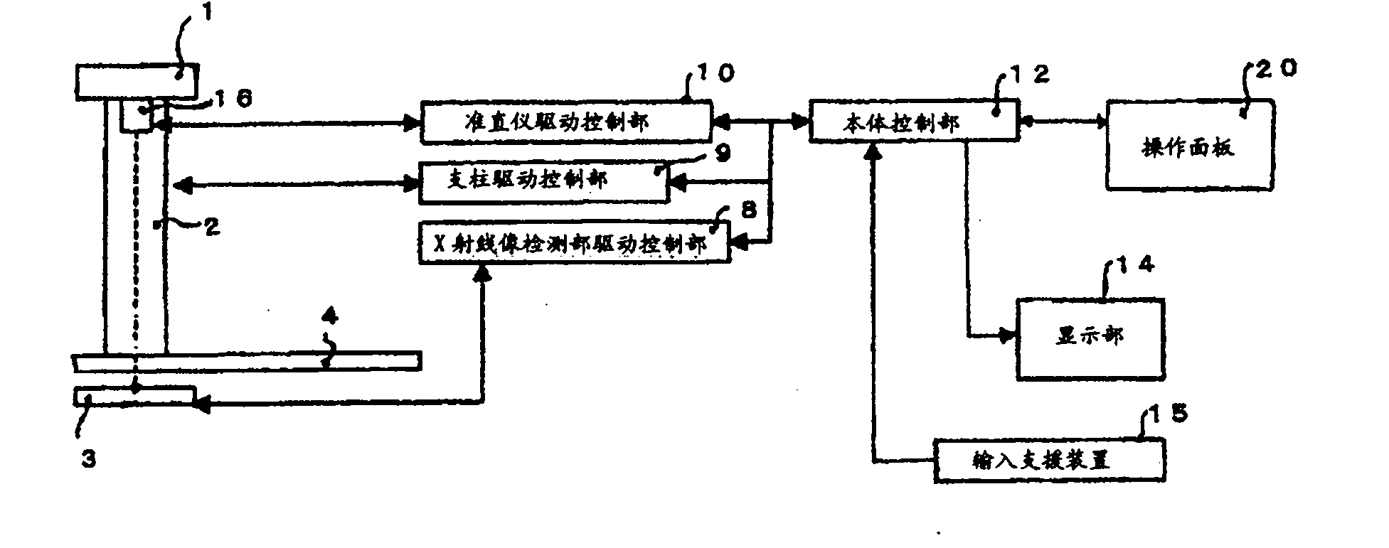
[0052] use Figure 1 to Figure 5 Example 1 of the present invention will be described. figure 2 Is a diagram showing an example of the external appearance of the X-ray fluoroscopy imaging apparatus according to the first embodiment of the present invention, image 3 It is a block diagram for explaining the control part and the operation part which control the characteristic operation|movement of Example 1 of this invention. In addition Figure 4 Is a diagram showing a display example of the display unit 14, figure 1 It is a figure for demonstrating the positional relationship of the X-ray tube apparatus 1 and the X-ray image detection part 3 mutually linked.

[0053] The X-ray fluoroscopic imaging apparatus of Embodiment 1 of the present invention, for example figure 2 Shown includes a top plate 4, an X-ray tube device 1, an X-ray diaphragm 16, and an X-ray image detection unit 3, etc., wherein the top plate 4 is held by a main pillar 5 vertically erected on the ...

Example Embodiment

[0066] Example 2

[0067] use Figure 4 versus Figure 6 to Figure 9 Example 2 of the present invention will be described. Figure 7 Is a diagram showing an example of the appearance of an X-ray fluoroscopy imaging apparatus according to Embodiment 2 of the present invention, Figure 8 It is a block diagram for explaining the control part and the operation part which control the characteristic operation|movement of Embodiment 2 of this invention. In addition, Figure 4 Is a diagram showing a display example of the display unit 14, Image 6 It is a figure for demonstrating the positional relationship of the X-ray tube apparatus 1 and the X-ray image detection part 3 which interlock|cooperate.

[0068] The X-ray fluoroscopy imaging device of Embodiment 2 of the present invention, for example Figure 7 Shown includes: a top plate 4, a support arm 26, an X-ray tube device 1, an X-ray diaphragm 16, and an X-ray image detection unit 3, etc., wherein the top plate 4 is vertically erected ...


PUM


Abstract

When urinary organ contrasting inspection is performed using a fluoroscopy for digestive organs, an region of interest such as a bladder often comes to the vicinity of the foot side end of a top plate, and since an X-ray tube device and an X-ray image detecting section are interlocked such that the focal point of the X-ray tube device comes directly above the central position of the X-ray image detecting section, the focal point often fails to be located directly above the region of interest in the vicinity of the foot side end of the top plate. Consequently, it is often the case that the irradiation field cannot be limited to a suitable area to the region of interest and only oblique photography can be performed. When urinary organ contrasting inspection is performed, an X-ray tube device (1), an X-ray diaphragm (16) and an X-ray image detecting section (3) are interlocked such that the foot side end of irradiation field matches the foot side end of the X-ray image detecting section (3). Consequently, the focal point (1A) of the X-ray tube device (1) can be moved directly above the foot side end of the X-ray image detecting section (3).

Description

technical field [0001] The invention relates to an X-ray perspective photography device. Background technique [0002] X-ray fluoroscopy devices for the digestive tract, such as figure 2 Shown is composed of a top plate (top plate) 4, an X-ray tube device (X-ray tube device) 1, an X-ray diaphragm (X-ray diaphragm) 16, and an X-ray image detecting section (X-ray image detecting section) 3, etc. constitute. The top plate 4 is held by a main pillar 5 vertically erected on the floor via a base 6, and a subject (not shown) is placed thereon. The X-ray tube device 1 is held by an arm 26 attached to a support 2 , and the support 2 is held movably in the longitudinal direction of the top plate 4 by a main support 5 . The X-ray diaphragm 16 is attached to the X-ray irradiation part of the X-ray tube device 1 to open and close a rectangular irradiation field. The X-ray image detection unit 3 is disposed on the back of the top plate 4 facing the X-ray tube device 1, is held movably...

Claims


Application Information

Patent Timeline
IPC IPC(8): A61B6/00
CPCA61B6/4441A61B6/06A61B6/487A61B6/0421A61B6/587A61B6/4283A61B6/04A61B6/481
Inventor 增尾克裕田中雅大加藤三纪彦
Owner SHIMADZU CORP
Why Eureka
Try Eureka