Drill grinder

A technology of grinding machine and deceleration mechanism, used in grinding machines, grinding/polishing equipment, metal processing equipment, etc., can solve the problems of unsatisfactory taper surface, waste of steel resources, falling in stone caves, etc., and achieve processing costs. The effect of low power consumption and high work efficiency

Inactive Publication Date: 2010-08-18
潘双津 +1
View PDF6 Cites 2 Cited by
  • Summary
  • Abstract
  • Description
  • Claims
  • Application Information

AI Technical Summary

Problems solved by technology

However, since the taper of the drill rod and shank is processed by a lathe at present, the turning tool must use a hard alloy capable of turning hardened steel, and the amount of cutting must be small, which not only has low work efficiency, but also has high cost; in addition, some drill rods The processed cone surface does not meet the requirements. Some cone surfaces are short in length, and some taper is too large to exceed 0.5°, which may easily cause the trousers of the drill bit to fall into the cave or collapse the cone head of the drill rod and be scrapped. In addition, it may be scrapped due to various reasons such as breakage, collapse of the cone surface, blockage of water holes, and bending of large stones, resulting in waste of steel resources and economic losses.

Method used


Image

  • Drill grinder
  • Drill grinder

Examples


Embodiment Construction

[0018] Below in conjunction with accompanying drawing, the present invention will be further elaborated:

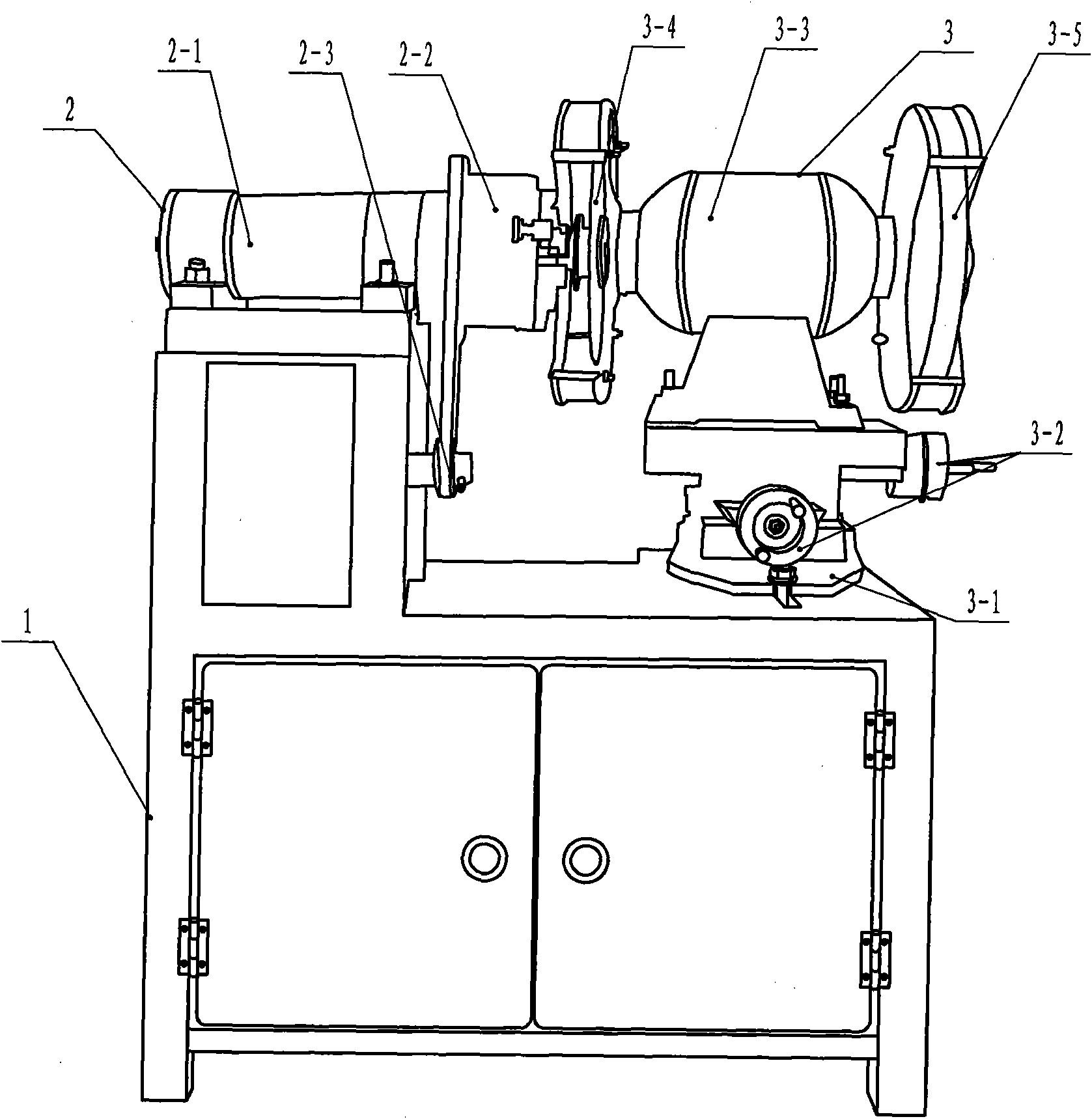
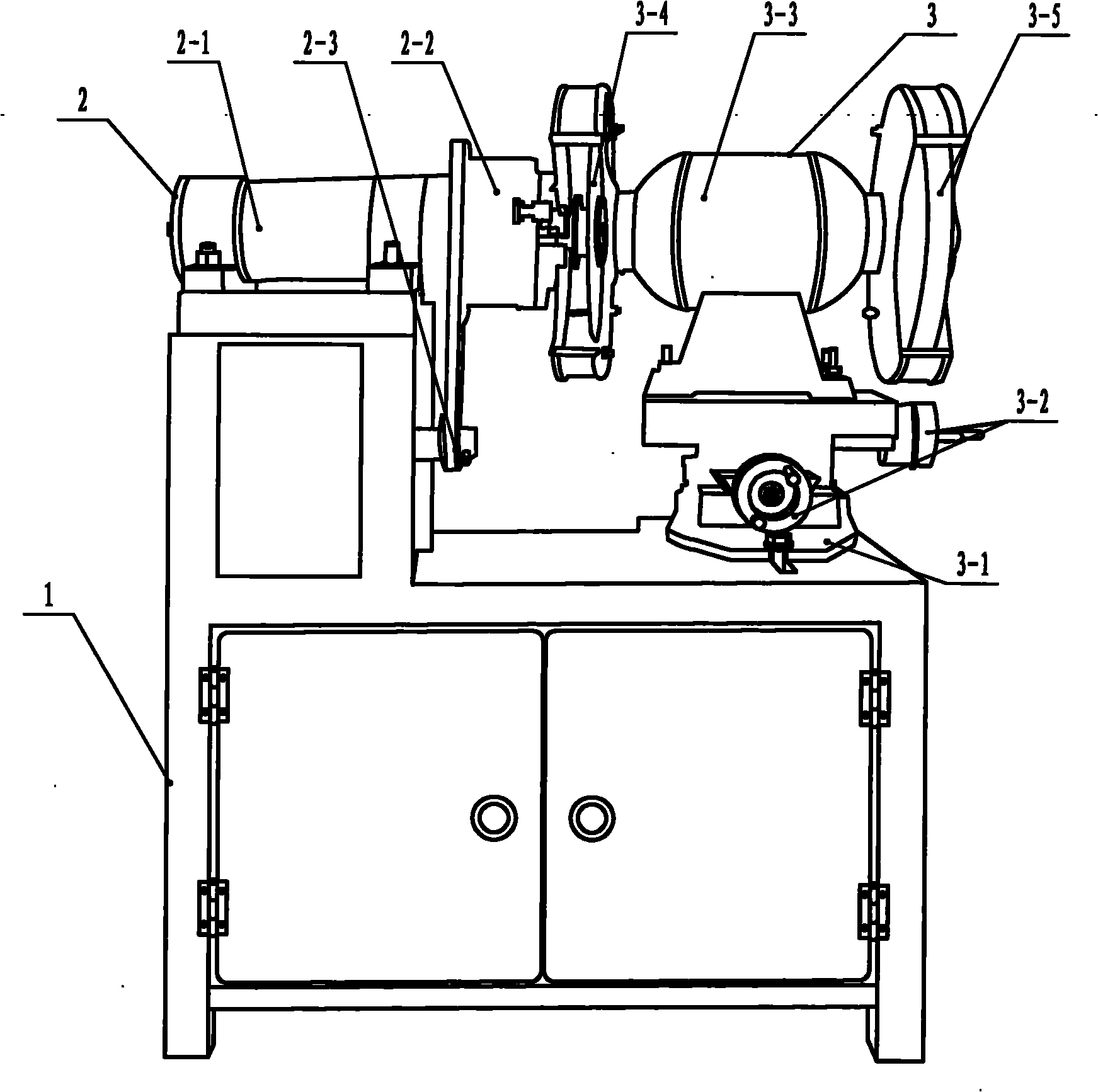
[0019] The brazing machine of the present invention consists of a counter 1, a chuck mechanism 2 fixedly connected to the counter 1 and a rotating cross table 3 opposite to the chuck mechanism 2 on the counter 1.

[0020] The chuck mechanism 2 is composed of the spindle cylinder 2-1, the chuck 2-2 abutted against the spindle cylinder 2-1 and the reduction mechanism 2-3 in the counter 1 connected with the chuck 2-2 and the reduction mechanism 2-3 connected with the reduction mechanism 2-1. 3 connected motors.

[0021] The lower part of the rotary cross table 3 is an angle rotating disk 3-1, the bottom surface of the angle rotating disk 3-1 is fixedly connected with the counter 1, and the X-axis and Y-axis workbenches that can move horizontally and vertically are set on the angle rotating disk 3-1 3-2. A grinder 3-3 is installed on the X-axis and Y-axis table 3-2. The outp...


PUM


Abstract

The invention discloses a drill grinder, which is characterized by consisting of a counter, a chuck mechanism fixedly connected to the counter and a rotary cross workbench which is arranged on the counter and opposite to the chuck mechanism. The drill grinder has the advantages of low cost, simple structure, compaction, light weight, simple operation, low power consumption, high working efficiency, suitability for grinding on a construction site, three functions of cutting, grinding a conical surface and grinding an alloy drill bit, great reduction in steel consumption and capital due to repair and reuse of waste drill bars, and stable size and angle, and high product quality because of using a grinding wheel for grinding the conical surface..

Description

technical field [0001] The invention relates to a grinding mechanical device, in particular to a brazing grinder suitable for grinding a brazing tool. Background technique [0002] Generally, mining of minerals and stones requires drill rods to drill holes and put explosives. The amount of drill rods in the country is very large, and a large amount of high-quality steel is required. However, since the taper of the drill rod and shank is processed by a lathe at present, the turning tool must use a hard alloy capable of turning hardened steel, and the amount of cutting must be small, which not only has low work efficiency, but also has high cost; in addition, some drill rods The processed cone surface does not meet the requirements. Some cone surfaces are short in length, and some taper is too large to exceed 0.5°, which may easily cause the trousers of the drill bit to fall into the cave or collapse the cone head of the drill rod and be scrapped. In addition, it may be scrap...

Claims


Application Information

Patent Timeline
Patent Type & Authority Applications(China)
IPC IPC(8): B24B19/09
Inventor 潘双津薛秋成
Owner 潘双津
Why Eureka
Try Eureka