Vertical shaft wind wheel with multi-section combined vanes

A combined, vertical axis technology, applied in the field of wind rotors, can solve the problems of unable to reduce the resistance moment of the effective rotation of the blades and rotors, high investment and operating costs, and wind energy consumption, so as to achieve regular size, improve overall efficiency, The effect of less flow loss

Inactive Publication Date: 2010-08-18
UNIV OF SHANGHAI FOR SCI & TECH
View PDF4 Cites 4 Cited by
  • Summary
  • Abstract
  • Description
  • Claims
  • Application Information

AI Technical Summary

Problems solved by technology

[0004] A Chinese invention patent discloses a "wind wheel device for a vertical axis wind turbine", application number: 200710007899.X, application date: 2007.01.22, the curved surface formed by symmetrical partial circular planes is used as the blade of the wind wheel, With four or more such blades, the two acute angles of the blades are fixed and evenly connected together on the same wind rotor shaft in order to form a wind rotor with an appearance similar to a pumpkin, but the disadvantage of this device is that it cannot Reduce the resistance torque that is not conducive to the effective rotation of the wind wheel caused by the direct impact of the incoming flow on the suction surface of the blade
The semi-cylindrical wind regulating gate can change its position according to the wind direction to adjust the wind receiving area of ​​the blade. The utilization of the wind energy has reached the maximum value. In the effective wind area covered by the rotation of the wind turbine blades, the maximum utilization rate of wind energy can reach 50%. The wind wheel is turned off, but the disadvantage of this device is that although the addition of an adjustable gate has a certain energy-saving effect, the initial investment cost and operating cost are relatively high.
When the fluid flows through the wind rotor of this structure, due to the strong boundary layer friction loss on the upper and lower cover plates, the wind energy will be greatly consumed, which hinders its ability to convert into rotational mechanical energy
Therefore, the structural optimization of the upper and lower cover plates of the wind rotor will definitely have a positive impact on improving the aerodynamic effect of the entire wind rotor, but it is rarely mentioned in various domestic patents

Method used


Image

  • Vertical shaft wind wheel with multi-section combined vanes
  • Vertical shaft wind wheel with multi-section combined vanes

Examples


Embodiment Construction

[0018] The present invention will be described in detail below in conjunction with the accompanying drawings and embodiments. However, this embodiment is not intended to limit the present invention, and all similar structures and similar changes of the present invention should be included in the protection scope of the present invention.

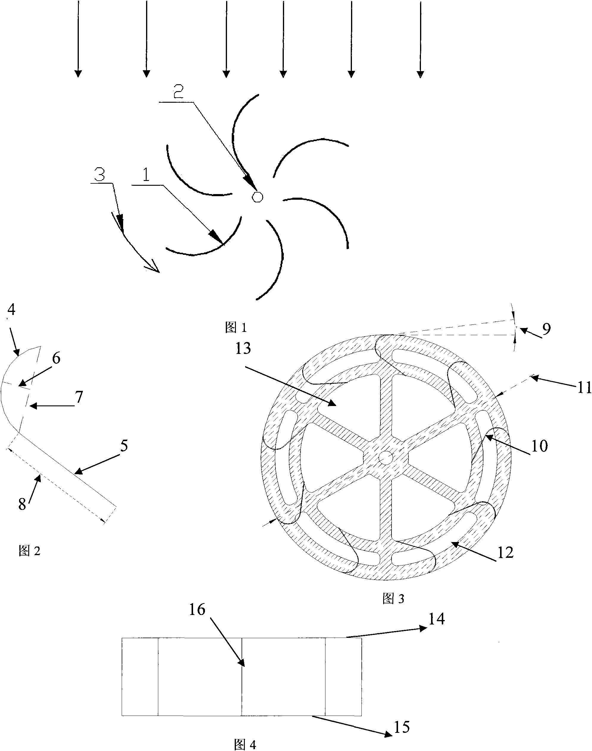
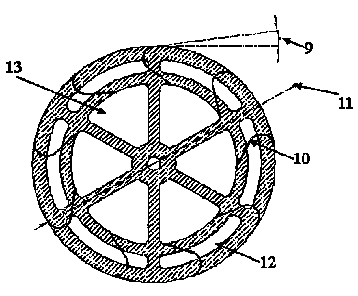
[0019] Such as figure 2 , 3 , Shown in 4: the vertical axis wind wheel with multi-section combined fan blades of the present invention comprises upper and lower cover plates 14,15, rotating shaft 16 and is made up of these two parts of inlet arc section 4 and outlet straight section 5 wind blade 10.

[0020] Nine multi-section combined wind blades 10 are installed between the upper and lower cover plates 14, 15 of the wind wheel, and are arranged at equal intervals along the circumferential direction; the wind blades 10 are straight blades with equal blade heights, and their inlet installation angle 9 is 0°~10°; the outlet straight secti...


PUM


Abstract

The invention relates to a vertical shaft wind wheel with multi-section combined vanes. A plurality of multi-section combined vanes are installed between an upper cover plate and a lower cover plate of the wind wheel and are arranged along the circumference at equal intervals; each vane comprises an inlet circular-arc section and an outlet straight-line section which are tangent end to end; and the vanes are straight vanes with equal heights, and the inlet installation angles of the vanes are 0 degree to 10 degrees. The ratio of the arch rise to the chord length of each inlet circular-arc sections is 0.35, and the chord length of each inlet circular-arc section is 0.75 times of the length of the corresponding outlet straight-line section and is 0.1 time of the diameter of the corresponding air wind; and an inner ring and an outer ring of ventilation holes with regular sizes are uniformly distributed on the upper cover plate and the lower cover plate, wherein the inner ring of ventilation holes are in a homalographic sector annular shape and are arranged along the circumference at equal intervals; and the outer ring of ventilation holes are in a homalographic arc shape and are arranged along the circumference at equal intervals. The invention has the advantages of strong wind energy collection, small flow loss, high pneumatic performance, simple process and the like, and a vertical shaft wind machine has the characteristics of high-efficient utilization rate of wind energy.

Description

technical field [0001] The invention relates to a wind rotor for a vertical axis wind turbine, in particular to a multi-section combined wind blade arranged at equal distances along the circumferential direction. Background technique [0002] The wind turbine is the power source of the wind power generation system, which converts wind energy into mechanical energy, and then drives the generator to generate electricity. According to the structural form, wind turbines are generally divided into two types: horizontal axis and vertical axis. The horizontal axis wind turbine has been well developed and has been widely used as the mainstream type of wind turbine because of its high efficiency. However, due to the disadvantages of high installation difficulty, high investment cost, and inconvenient movement of horizontal axis wind turbines, its use is currently mainly limited to grid-connected power generation. For some small off-grid power generation systems, the most widely used...

Claims


Application Information

Patent Timeline
Patent Type & Authority Applications(China)
IPC IPC(8): F03D3/06
CPCY02E10/74
Inventor 王企鲲王鑫
Owner UNIV OF SHANGHAI FOR SCI & TECH
Why Eureka
Try Eureka