
Over-fire-air device for different load pulverized-coal fired boilers

A technology of burnout air and pulverized coal, which is used in combustion equipment, lighting and heating equipment, etc., can solve the problems of weakened penetration, reduced burnout air momentum, and uneven mixing of burnout air.

Inactive Publication Date: 2010-08-18
HARBIN INST OF TECH
View PDF8 Cites 5 Cited by
  • Summary
  • Abstract
  • Description
  • Claims
  • Application Information

AI Technical Summary

Problems solved by technology

[0005] The present invention aims to solve the problem that the momentum of the overfired air is reduced, the penetrating power is weakened, and the overfired air is mixed unevenly in the flow field when the pulverized coal boiler using the existing overfired air device operates at different loads, especially at low loads, resulting in The content of fly ash combustibles in flue gas is high, NO x content, etc., and then proposed a kind of overfire air device suitable for pulverized coal boilers with different loads

Method used


Image

  • Over-fire-air device for different load pulverized-coal fired boilers
  • Over-fire-air device for different load pulverized-coal fired boilers
  • Over-fire-air device for different load pulverized-coal fired boilers

Examples


specific Embodiment approach 1

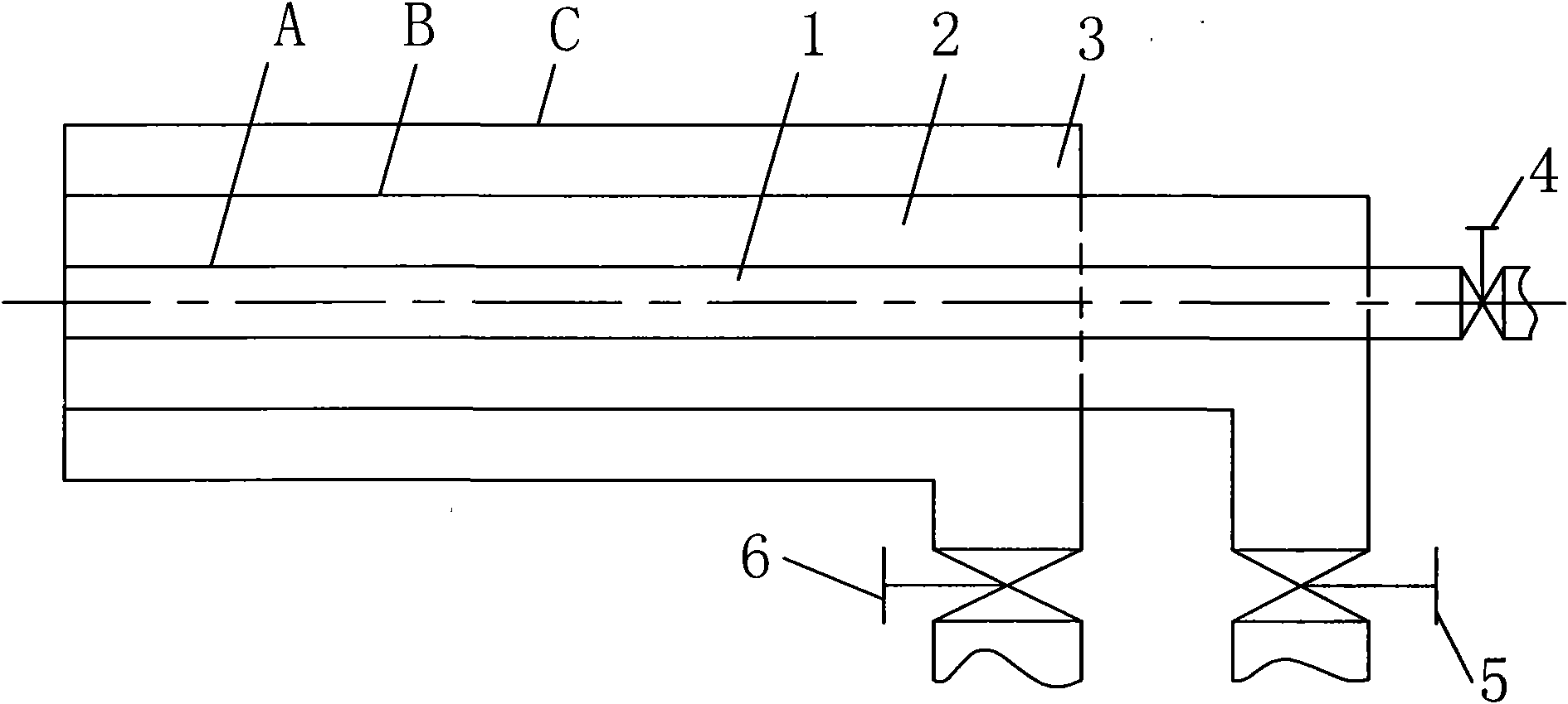
[0013] Specific implementation mode one: combine figure 1 Describe this embodiment. The overfire air device applicable to pulverized coal boilers with different loads described in this embodiment includes an inner air duct A, an intermediate air duct B, an outer air duct C, an inner air duct valve 4, and an intermediate air duct valve 5 and the outer air duct valve 6; the inner air duct A, the middle air duct B, and the outer air duct C are set sequentially from the inside to the outside and the three are coaxially arranged, and the inner cavity of the inner air duct A is an internal combustion exhaust air duct 1. The annular cavity between the outer surface of the inner air duct A and the inner wall surface of the intermediate air duct B is the intermediate overfired air duct 2. The space between the outer surface of the intermediate air duct B and the inner wall surface of the outer air duct C The annular cavity is the external burn-out air duct 3, the inner air duct valve 4...

specific Embodiment approach 2

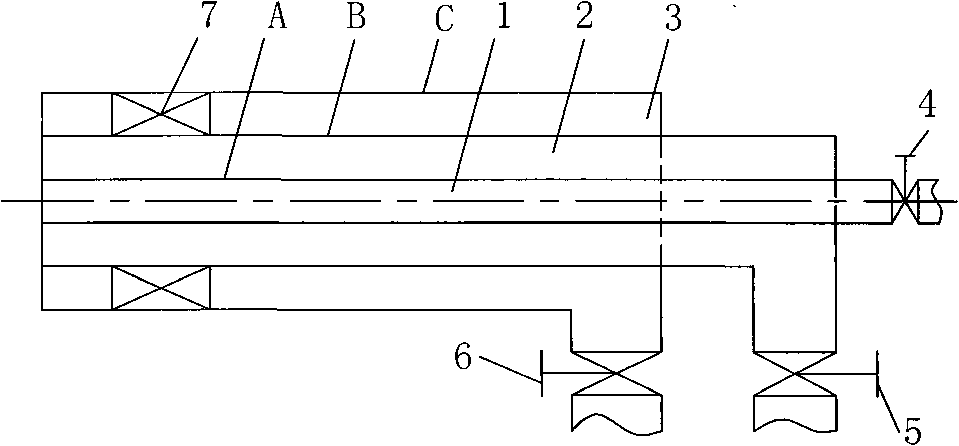
[0015] Specific implementation mode two: combination figure 2 To illustrate this embodiment, the over-burning air device in this embodiment further includes the swirl blades 7 of the outer air passage, and the swirling blades 7 of the outer air passage are arranged in the outer over-combustion air duct 3 . Both the internal overcombustion air duct 1 and the intermediate overcombustion air duct 2 of the present embodiment are used as direct-flow air ducts, and the external over-combustion air duct 3 is used as a swirl air duct, and the wind flowing out from the swirl air duct is swirl wind. The wind flowing out of the duct is direct current wind; the direct current wind has large axial momentum and strong penetrating power, and can mix and diffuse with the furnace flue gas at a distance from the burnout air nozzle; the axial momentum of the swirl wind is smaller than that of the direct current wind, Moreover, the swirling air has a tangential velocity, which can mix and diffus...

specific Embodiment approach 3

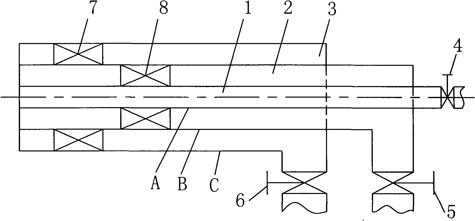
[0017] Specific implementation mode three: combination image 3To illustrate this embodiment, the over-fired air device in this embodiment further includes the swirl blades 8 in the middle air passage, and the swirl blades 8 in the middle air passage are arranged in the middle over-fired air passage 2 . The internal overcombustion air duct 1 of this embodiment is used as a straight air duct, and the middle overcombustion air duct 2 and the external overcombustion air duct 3 are all used as swirl air ducts; the wind flowing out from the swirl air duct is swirl wind, and The wind flowing out of the duct is direct current wind; the direct current wind has large axial momentum and strong penetrating power, and can mix and diffuse with the furnace flue gas at a distance from the burnout air nozzle; the axial momentum of the swirl wind is smaller than that of the direct current wind, Moreover, the swirling air has a tangential velocity, which can mix and diffuse with the furnace flu...


PUM


Abstract

The invention relates to an over-fire-air device for different load pulverized-coal fired boilers, and to an over-fire-air device, which solves the problems of the pulverized-coal fired boiler by utilizing the present over-fire-air device that when the load is different and particularly when the device runs at a low load, the over-fire-air momentum is reduced, the penetrating power is weakened, the mixing of the over-fire-air is non-uniform in the flow field, the ash combustible substance content in the smoke is high, the content of NOx is high, and the like. An inner air-course valve is arranged at an entrance of an inner over-fire-air air course, an intermediate air-course valve is arranged at an entrance of an intermediate over-fire-air air course, and an outer air-course valve is arranged at an entrance of an outer over-fire-air air course. A share air-course valve is arranged at the communication place of the intermediate and the outer over-fire-air air courses. An intermediate air-course valve is arranged at the entrance of the intermediate over-fire-air air course, and an outer air-course valve is arranged at the entrance of the outer over-fire-air air course. By adjusting the openness of the valves, and under the high load and the low load, good combustion effect can be realized, while the NOx content is reduced.

Description

technical field [0001] The invention relates to an overburning air device, which belongs to the technical field of combustion of pulverized coal boilers. Background technique [0002] NO emissions from thermal power plants x are the three major flue gas pollutants (SO x , NO x and total suspended particulate matter (TSP), has brought a series of environmental pollution problems, seriously endangering the ecological balance and human survival. At present, for most domestic active boilers that do not use overfired air, the NO x The emission level is mostly at 600mg / m 3 around, NO from burning lean coal x The emission level is mostly at 1000mg / m 3 around, the NO of burning low volatile coal x The emission level is mostly at 2000mg / m 3 about. With the increasingly stringent national and local environmental protection policies, various means are used to reduce boiler NO x Emissions are getting more and more attention. [0003] To reduce NO in furnace flue gas x The co...

Claims


Application Information

Patent Timeline
IPC IPC(8): F23C7/00
Inventor 陈智超李争起曾令艳朱群益邢超胡志勇徐振新申珊平孔维光
Owner HARBIN INST OF TECH
Learn More